
You are here: Start » Machine Vision Guide » Camera Calibration and World Coordinates
Camera Calibration and World Coordinates
Camera Calibration
Camera calibration, also known as camera resectioning, is a process of estimating parameters of a camera model: a set of parameters that describe the internal geometry of image capture process. Accurate camera calibration is is essential for various applications, such as multi-camera setups where images relate to each other, removing geometric distortions due to lens imperfections, or precise measurement of real-world geometric properties (positions, distances, areas, straightness, etc.).
The model to be used is chosen depending on the camera type (e.g. projective camera, telecentric camera) and accuracy requirements. In a case of a standard projective camera, the model (known as pinhole camera model) consists of focal length, principal point location and distortion parameters.
A few distortion model types are supported. The simplest - divisional - supports most use cases and has predictable behaviour even when calibration data is sparse. Higher order models can be more accurate, however they need a much larger dataset of high quality calibration points, and are usually needed for achieving high levels of positional accuracy across the whole image - order of magnitude below 0.1 pix. Of course this is only a rule of thumb, as each lens is different and there are exceptions.
The camera model contains only intrinsic camera parameters, and so it does not change with camera repositioning, rotations, etc. Thanks to that, there is no need for camera calibration in the production environment, the camera can be calibrated beforehand. As soon as the camera has been assembled with the lens and lens adjustments (zoom/focus/f-stop rings) have been tightly locked, the calibration images can be taken and camera calibration performed. Of course any modifications to the camera-lens setup void the calibration parameters, even apparently minor ones such as removing the lens and putting it back on the camera in seemingly the same position.
Camera model can be directly used to obtain an undistorted image (an image, which would have been taken by a camera with the same basic parameters, but without lens distortion present), however for most use cases the camera calibration is just a prerequisite to some other operation. For example, when camera is used for inspection of planar surfaces (or objects lying on such surface), the camera model is needed to perform a World Plane calibration (see World Plane - measurements and rectification section below).
In Adaptive Vision Studio user will be prompted by a GUI when a camera calibration is needed to be performed. Alternatively, filters responsible for camera calibration may be used directly: CalibrateCamera_Pinhole, CalibrateCamera_Telecentric.
 |
 |
 |
||
 |
 |
 |
||
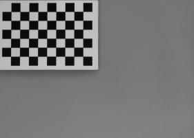
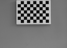
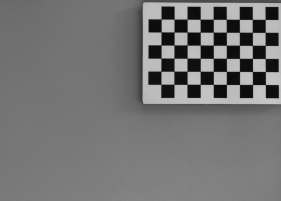
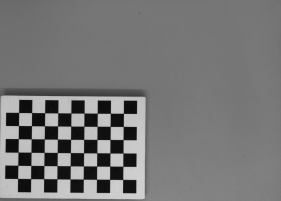
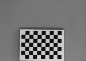
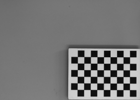
A set of grid pictures for basic calibration. Note that high accuracy applications require denser grids and higher amount of pictures. Also note that all grids are perpendicular to the optical axis of the camera, so the focal length won't be calculated by the filter. |
||||
World Plane - Measurements and Rectification
Vision systems which are concerned with observation and inspection of planar (flat) surfaces, or objects lying on such surfaces (e.g. conveyor belts) can take advantage of the image to world plane transform mechanism of Adaptive Vision Studio, which allows for:
- Calculation of real world coordinates from locations on original image. This is crucial, for example, for interoperability with external devices, such as industrial robots. Suppose a object is detected on the image, and its location needs to be transmitted to the robot. The detected object location is given in image coordinates, however the robot is operating in real world with different coordinate system. A common coordinate system is needed, defined by a world plane.
- Image rectification onto the world plane. This is needed when performing image analysis using original image is not feasible (due to high degree of lens and/or perspective distortion). The results of analysis performed on a rectified image can also be transformed to real-world coordinates defined by a world plane coordinate system. Another use case is a multi-camera system – rectification of images from all the cameras onto common world plane gives a simple and well defined relation between those rectified images, which allows for easy superimposing or mosaic stitching.
The image below shows the image coordinate system. Image coordinates are denoted in pixels, with the origin point (0, 0) corresponding to the top-left corner of the image. The X axis starts at the left edge of an image and goes towards the right edge. The Y axis starts at the top of the image towards image bottom. All image pixels have nonnegative coordinates.
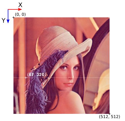
Directions and pixel positions in image coordinates.
The world plane is a distinguished flat surface, defined in the real 3D world. It may be arbitrarily placed with respect to the camera. It has a defined origin position and XY axes.
Images below present the concept of a world plane. First image presents an original image, as captured by a camera that has not been mounted quite straight above the object of interest. The second image presents a world plane, which has been aligned with the surface on which the object is present. This allows for either calculation of world coordinates from pixel locations on original image, or image rectification, as shown on the next images.
Object of interest as captured by an imperfectly positioned camera.
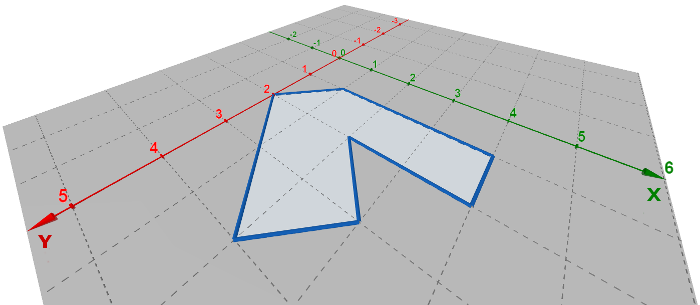
World plane coordinate system superimposed onto the original image.
 |
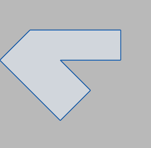 |
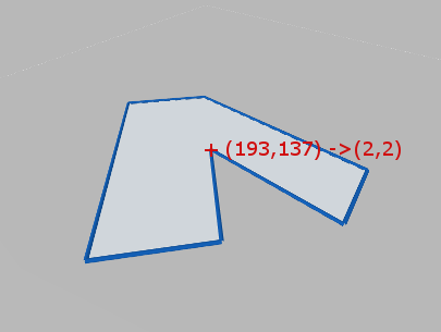
Image to world plane coordinate calculation. |
Image rectification, with cropping to an area from point (0,0) to (5,5) in world coordinates. |
In order to use the image to world plane transform mechanism of Adaptive Vision Studio, appropriate UI wizards are supplied:
- For calculation of real world coordinates from locations on original image – use a wizard associated with the inTransform input of ImagePointToWorldPlane filter (or other from ImageObjectsToWorldPlane group).
- For image rectification onto the world plane – use a wizard associated with the inRectificationMap input of RectifyImage filter.
Although using UI wizards is the recommended course of action, the most complicated use cases may need a direct use of filters, in such a case following steps are to be performed:
- Camera calibration – this step is highly recommended to achieve accurate results, although not strictly necessary (e.g. when lens distortion errors are insignificant).
- World plane calibration – the CalibrateWorldPlane filters compute a RectificationTransform, which represents image to world plane relation
- The image to world plane relation then can be used to:
- Calculate of real world coordinates from locations on original image, and vice versa, see ImagePointToWorldPlane, WorldPlanePointToImage or similar filters (from ImageObjectsToWorldPlane or WorldPlaneObjectsToImage groups).
- Perform image rectification onto the world plane, see CreateRectificationMap filters.
Usual use cases perform either calculation of world coordinates from pixel locations on original image, or image rectification. However, in some cases it is needed to calculate world coordinates of pixel locations on rectified image. In such a case, after performing analysis on an rectified image (i.e. image remapped by RectifyImage), the locations can be transformed to a common coordinate system given by the world plane by using the rectified image to world plane relation. It is given by auxiliary output outRectifiedTransform of RectifyImage filter. Notice that the rectified image to world plane relation is different than original image to world plane relation.
 |
 |
|||
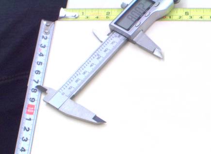
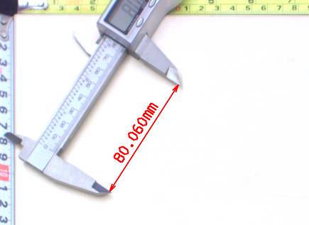
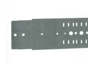
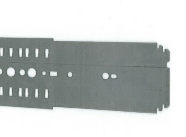
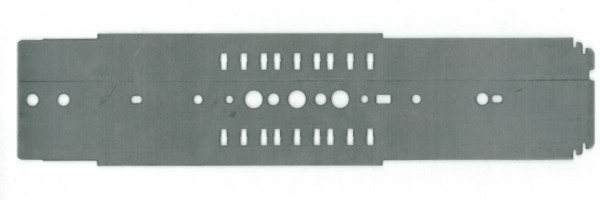
Example of taking world plane measurements on the rectified image. Left: original image, as captured by a camera, with mild lens distortion. Right: rectified image with annotated length measurement. |
||||
Notes:
- Image to world plane transform is still a valid mechanism for telecentric cameras. Is such a case, the image would be related to world plane by an affine transform.
- Camera distortion is automatically accounted for in both world coordinate calculations and image rectification.
- The spatial map generated by CreateRectificationMap filters can be thought of as a map performing image undistortion followed by a perspective removal.
Extraction of Calibration Grids
Both camera calibration and image to world plane transform calculation use extracted calibration grids in the form of array of image points with grid indices, i.e. annotated points.
Note that the real-world coordinates of the grids are 2D, because the relative \(z\) coordinate of any point on the flat grid is \(0\).
Adaptive Vision Studio provides extraction filters for a few standard grid formats (see: DetectCalibrationGrid_Chessboard and DetectCalibrationGrid_Circles).
Using custom grids requires a custom solution for extracting the image point array. If the custom grid is a rectangular grid, the AnnotateGridPoints filter may be used to compute annotations for the image points.
Note that the most important factor in achieving high accuracy results is the precision and accuracy of extracted calibration points. The calibration grids should be as flat and stiff as possible (cardboard is not a proper backing material, thick glass is perfect). Take care of proper conditions when taking the calibration images: minimize motion blur by proper camera and grid mounts, prevent reflections from the calibration surface (ideally use diffusion lighting). When using a custom calibration grid, make sure that the points extractor can achieve subpixel precision. Verify that measurements of the real-world grid coordinates are accurate. Also, when using a chessboard calibration grid, make sure that the whole calibration grid is visible in the image. Otherwise, it will not be detected because the detection algorithm requires a few pixels wide quiet zone around the chessboard. Pay attention to the number of columns and rows, as providing misleading data may make the algorithm work incorrectly or not work at all.
The recommended calibration grid to use in Adaptive Vision Studio is a circles grid, see DetectCalibrationGrid_Circles. Optimal circle radius may vary depending on exact conditions, however a good rule of thumb is 10 pixels (20 pixel diameter). Smaller circles tend to introduce positioning jitter. Bigger circles lower the total amount of calibration points and suffer from geometric inaccuracies, especially when lens distortion and/or perspective is noticeable.
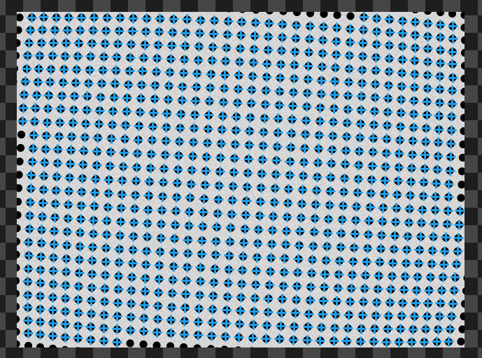
The circle grid is the recommended one to use in Adaptive Vision Studio.
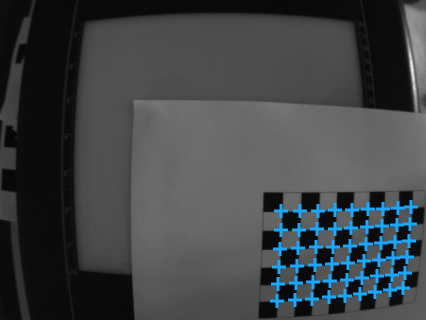
Detected chessboard grid, with image point array marked.
Please refer to Preparing Rectification Map Transform to get step-by-step instruction on how to perform calibration with the calibration editor (plugin).
Application Guide – Image Stitching
Seamless image stitching in multiple camera setup is, in its essence, an image rectification onto the world plane.
Note that high quality stitching requires a vigilant approach to the calibration process. Each camera introduces both lens distortion as well as perspective distortion, as it is never positioned perfectly perpendicular to the analyzed surface. Other factors that need to be taken into account are the camera-object distance, camera rotation around the optical axis, and image overlap between cameras.
The process consists of two main steps. First, each camera is calibrated to produce a partial, rectified image. Then all partial images are simply merged using the JoinImages filter.
Image stitching procedure can be outlined as follows:
- Cover the inspection area with two or more cameras. Make sure that fields of view of individual cameras overlap a bit.
- Place a calibration grid onto the inspection area. For each camera, capture the image of a part of the calibration grid. The grid defines a world coordinate system used for stitching, and so it should contain some markers from which the coordinates of world plane points will be identifiable for every camera.
- Define the world coordinate extents for which each camera will be responsible. For example, lets define that camera 1 should cover area from 100 to 200 in X, and from -100 to 100 in Y coordinate; camera 2 - from 200 to 300 in X, and from -100 to 100 in Y.
- For each camera, use a wizard associated with the inRectificationMap input of RectifyImage filter to setup the image rectification. Use the captured image for camera calibration and world to image transform. Use the defined world coordinate extents to setup the rectification map generation (select "world bounding box" mode of operation). Make sure that the world scale for rectification is set to the same fixed value for all images.
- Use the JoinImages appropriately to merge outputs of RectifyImage filters.
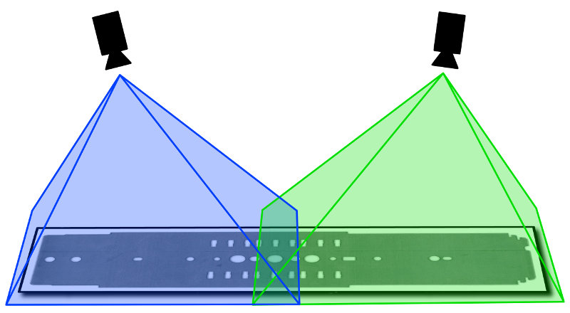
A multi-camera setup for inspection of a flat object.
 |
 |
|||
Input images, as captured by cameras. |
||||
Stitching result.
| Previous: Optical Character Recognition | Next: Golden Template |