
You are here: Start » Filter Reference » Camera Calibration » CalibrateCamera_Pinhole
CalibrateCamera_Pinhole

Finds the camera intrinsic parameters from the input arrays of annotated image coordinates. Uses pinhole camera model (perspective camera).
| Name | Type | Range | Description | |
|---|---|---|---|---|
 |
inImageGrids | AnnotatedPoint2DArrayArray | For each view, the annotated calibration grid | |
|
inImageWidth | Integer | 1 -  |
Image width, used for initial estimation of principal point. |
|
inImageHeight | Integer | 1 - |
Image height, used for initial estimation of principal point. |
|
inDistortionType | LensDistortionModelType | Lens distortion model | |
|
inImagePointsStandardDeviation | Real | 0.0 - |
Assumed uncertainty of inImagePoints. Used for robust optimization and outCameraModelStdDev estimation. |
|
inFocalLength | Real* | Specify a fixed focal length (do not estimate), in pixels. In order to calculate the inFocalLength from camera parameters one needs to divide the lens focal length [mm] by sensor pitch [mm/pix]. | |
 |
outCameraModel | PinholeCameraModel | ||
|
outCameraModelStdDev | PinholeCameraModel | Standard deviations of all model parameters, assuming that inImagePoints positions have a standard deviation equal to inImagePointsStandardDeviation. | |
|
outRmsError | Real | Final reprojection RMS error, in pixels. | |
|
outMaxReprojectionErrors | RealArray | For each view: the maximum reprojection error among all points. | |
|
outReprojectionErrorSegments | Segment2DArrayArray | For each view: array of segments connecting input image points to grid reprojections. | |
Applications
Description
The filter estimates intrinsic camera parameters - focal length, principal point location and distortion coefficients from a set of planar calibration grids by means of robust minimization of RMS reprojection error - the square root of averaged squared distances between grid points as observed on the image and their associated grid coordinates projected onto image plane using estimated parameters (i.e. grid poses and camera parameters).
The focal length can be calculated by the filter if at least one calibration grid is not perpendicular to the optical axis of the camera. Alternatively, the focal length can be set to a fixed value via inFocalLength. The inFocalLength is measured in pixels, it can be calculated from the sensor and lens parameters:

where f_pix - focal length measured in pixels, f_lens - focal length of lens measured in millimeters, pp - sensor pixel pitch measured in millimeters per pixel, d - camera binning or/and image downscaling factor
The inFocalLength can also be obtained from angle of view, for horizontal case following equation applies:
where f_pix - focal length measured in pixels, w - image width, alpha - horizontal angle of view
A few distortion model types are supported. The simplest - divisional - supports most use cases and has predictable behaviour even when calibration data is sparse. Higher order models can be more accurate, however they need a much larger dataset of high quality calibration points, and are usually needed for achieving high levels of positional accuracy across the whole image - order of magnitude below 0.1 pix. Of course this is only a rule of thumb, as each lens is different and there are exceptions.
Distortion model types are compatible with OpenCV, and are expressed with equations using normalized image coordinates:
Divisional distortion model
Polynomial distortion model
PolynomialWithThinPrism distortion model
where  , x' and y' are undistorted, x'' and y'' are distorted normalized image coordinates.
Although every application should be evaluated separately the general guidelines for choosing the right distortion type you will find in table below:
Required calibration data: |
Typical application: | Suggested Lens type: | |||
|---|---|---|---|---|---|
| Quality: | Quantity: | ||||
| Distortion model | Divisional | Average | Average | Robot Guidance | Pinhole |
| Polynomial | Very high. Calibration plate should be made of stiff material like metal plate or glass. | Very high evenly distributed across entire ROI. Calculation on areas not covered with calibration plate might be highly inaccurate. | Metrology | Pinhole/Telecentric | |
| Polynomial with thin prism | Metrology in micrometers | Telecentric | |||
The filter provides a few methods for judging the feasibility of calculated solution.
- The outRmsError is the final RMS reprojection error. The main contributor to that value is the random noise in inImageGrids points positions. Model mismatch will also result in increased outRmsError.
- The outMaxReprojectionErrors is an array of maximum reprojection errors, per view. It can be used to find suspicious calibration grids.
- The outCameraModelStdDev contains standard deviations of all parameters of estimated model, assuming that inImageGrids points positions have a standard deviation equal to inImagePointsStandardDeviation. It can be used to verify the stability of estimated parameters. High values may be a result of data deficiency in a sensitive region (e.g. lack of calibration points at the edges of image when high-order distortion model is used).
- The outReprojectionErrorSegments consists of segments connecting input image points to reprojected world points, and thus it can be readily used for visualization of gross errors. The XY scatter plot of residual vectors (obtained by using SegmentVector on the outReprojectionErrorSegments) is a good insight into the residuals distribution, which in ideal case should follow a 2D gaussian distribution centered around point (0,0).
Hints
- High accuracy camera calibration needs a considerable amount of high quality calibration points, especially when using more complicated models. Each calibration image should contain hundreds of calibration points, there should be at least a dozen of calibration images, and all the calibration points should span the area/volume of interest. The calibration grids should be as flat and stiff as possible (cardboard is not a proper backing material, thick glass is perfect). Take care of proper conditions when taking the calibration images: minimize motion blur by proper camera and grid mounts, prevent reflections from the calibration surface (ideally use diffusion lighting).
- There is no need for camera calibration in the production environment, the camera can be calibrated beforehand. As soon as the camera has been assembled with the lens and lens adjustments (zoom/focus/f-stop rings) have been tightly locked, the calibration images can be taken and camera calibration performed. Of course any modifications to the camera-lens setup void the calibration parameters, even apparently minor ones such as removing the lens and putting it back on the camera in seemingly the same position.
- Calibration set containing images of calibration grids that are not perpendicular to the optical axis of the camera allow for automatic focal length estimation. When all calibration grids are perpendicular to the optical axis of the camera and the focal length of the camera is not provided via inFocalLength, the calculated model will lack that value. Despite that, some operations will still work properly, such as distortion removal, or basic image to world plane calibration (CalibrateWorldPlane).
- Note that the pinhole camera calibration doesn't require scale information for its input calibration grids, e.g. when using DetectCalibrationGrid_Chessboard for grid detection, its inWorldSquareSize input has no effect on the calibration. Relative scale information between the grid dimensions is still crucial, e.g. when using non-square grid, the aspect ratio of point distances in perpendicular directions must be precisely known.
Examples
 |
 |
 |
||
 |
 |
 |
||
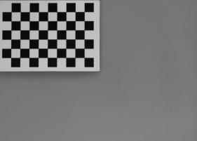
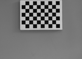
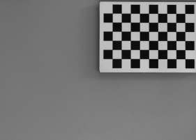
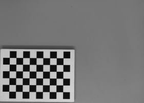
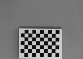
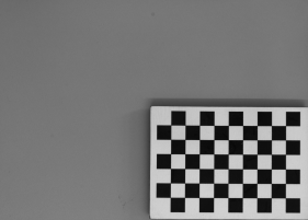
A set of grid pictures for basic calibration. Note that high accuracy applications require denser grids and higher amount of pictures. |
||||
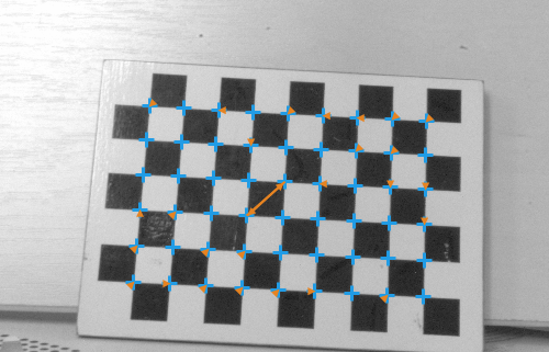
Usage of outReprojectionErrorSegments for identification of bad association of image points and their grid coordinates in inImageGrids - two points are swapped.
Errors
This filter can throw an exception to report error. Read how to deal with errors in Error Handling.
List of possible exceptions:
| Error type | Description |
|---|---|
| DomainError | Empty input grid array |
Complexity Level
This filter is available on Advanced Complexity Level.
Filter Group
This filter is member of CalibrateCamera filter group.
See Also
- CalibrateCamera_Telecentric – Finds the telecentric camera intrinsic parameters from the input arrays of annotated image coordinates.