
You are here: Start » Calibration of World Coordinates
Calibration of World Coordinates
Introduction
Adaptive Vision Studio provides tools to perform inspections on 2D images. Image analysis results are then passed to external devices like industrial robots or separators. In most cases, however, these devices work in different coordinate systems than the coordinate system of the image and use different measurement units (e.g. millimeters instead of pixels). For these reasons an appropriate calibration is required.
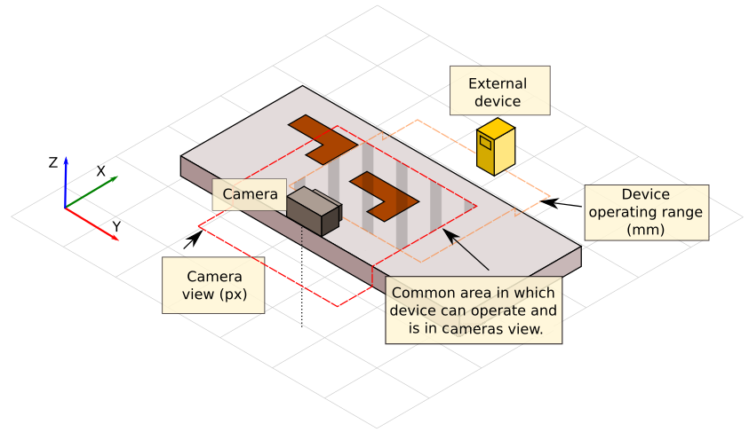
To send correct locations to an external device a calibration must be performed using points in common area marked on the image.
Image and World Coordinates
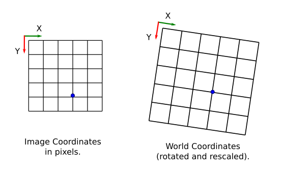
Image coordinates are denoted in pixels, with the origin point (0, 0) corresponding always to the top-left corner of the image. On the other hand world coordinates are denoted in real-world units, like millimeters, with the origin point placed at arbitrary location. Moreover, world coordinates can be three-dimensional and the plane of interest can be visible with perspective distortion. The task is to find the correspondence between the image and the world coordinates, and translate between ones and another.
The image below shows the basic coordinate values in image coordinates. The X axis starts at the left edge of an image and has maximal value at the right edge. The Y axis starts at the top of the image and ends at the bottom edge. This view is always shown in pixel units.
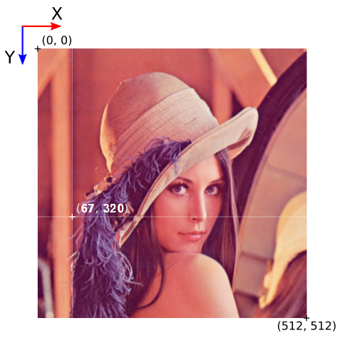
Directions and pixel positions in image coordinates.
Using Calibration
Image analysis tools of Adaptive Vision Studio operate in the image coordinate system. Before the results are passed to an external devices, they usually have to be translated to world coordinates. A typical example is when an object is found on an image and then its location should be passed to an industrial robot to pick it up.
Adaptive Vision Studio offers two ways of world coordinate calibration:
- Point-To-Point Calibration in which the model is created from known image points (2D) and the corresponding world points (3D). The filter CalibrateWorldCoordinates computes the world plane which can be later used to compute world points. Also world calibration resolution (inverse of scale) is found, which is necessary to calculate world points.
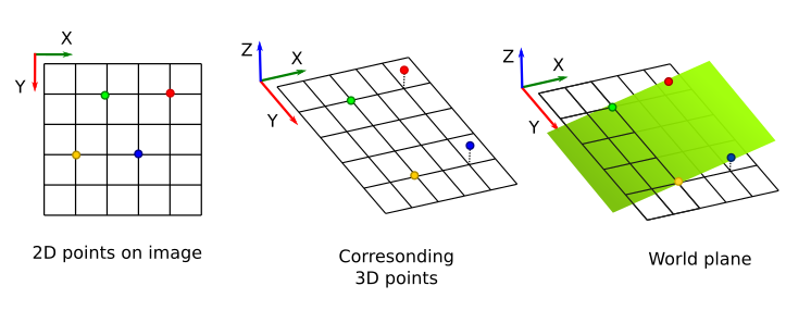
Finding a world plane using N pairs of points (at least four).
Image's points can be marked using an image as a background, but world points must be entered into the Properties Control manually.
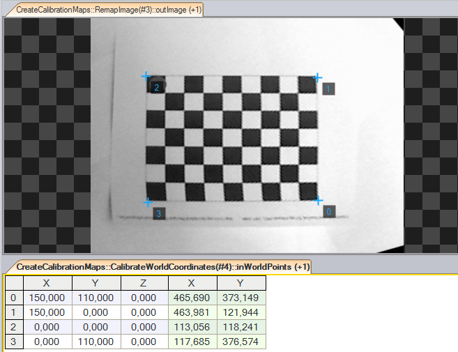
Configured pairs of image points (2D) and world points (3D).
- Calibration with explicit parameters in which only 2D translations, rotations and scaling is possible. This calibration can be done with the CoordinateSystem2DToPosition3D filter.
Creating a world calibration plane from the CoordinateSystem2D type.
Coordinate calibration model is represented by the Position3D type, which denotes the position of the plane-of-interest in the camera field of view. Calibration can be done once before the main program loop or in a separate program which saves it to a file for later use. Also resolution must be saved for the further usage.
Remarks:
- Coordinate calibration can take some time when many point pairs are used.
- If the calibration points are not consistent, then the world plane is approximated. Please always check if the calibration error lies in an expected range.
- In many cases the calibration resolution (inverse of scale) is different from 1.0 so it is necessary to save this parameter too.
Getting World Points
When the world plane is known basic geometric primitives can be converted to world coordinates. Adaptive Vision Studio offers the following conversion filters:
- PointToWorldCoordinates – converts a single Point2D to a single Point3D value,
- SegmentToWorldCoordinates – converts a Segment2D to an array of two 3D points (Point3DArray),
- PathToWorldCoordinates – converts a Path to an array of 3D points (Point3DArray).
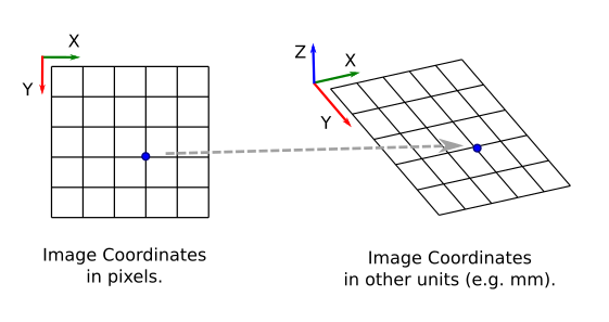
Converting a point from image to world coordinates using the PointToWorldCoordinates filter.
There is also the opposite filter, PointToImageCoordinates, which converts a 3D point to a point on an image.