
You are here: Start » Program Examples » Fiducial Markers
Fiducial Markers
Aim:
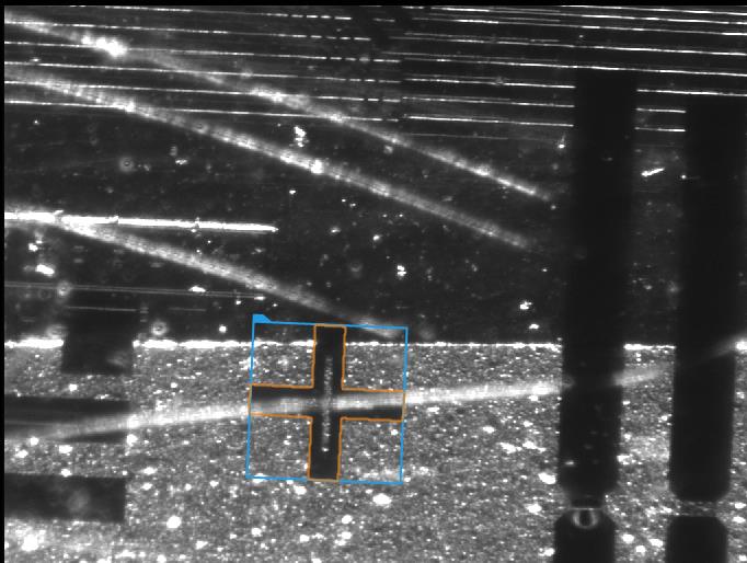
The goal of this task is to detect fiducial markers (in the shape of a plus sign) on different images. The markers have the same size, can be rotated, and can be both bright and dark.
Input:
An image of a fragment of an electronic board.

Output:
An image with the detected marker highlighted.
Hints:
The colors of neither the object to detect nor the background are constant. However, there is always a visible boundary, or edge, between the markers and the background.
Since none of the input images have a clear view of the marker, it may be useful to prepare an artificial image where it is easily noticeable.
Labeling connections is explained in this article.
Solution (AVS):
- In Workspace Explorer, open the workspace Examples, and in the Filmstrip window, select the FiducialMarker dataset. Drag the Image channel to the ACQUIRE section.
-
Since it would be difficult to create and edge model from one of the input images due to them being cluttered, we should create a training image. To do this, start by adding the EmptyImage filter.
- In the ReadFilmstrip filter, right click on the outImage, go to property outputs , and check both Height and Width .
- Connect the new outputs to the appropriate inputs in the EmptyImage.
- Run the program once to calculate the values of outputs.
-
Add the DrawPaths_SingleColor filter. Connect the output of the EmptyImage to the appropriate input
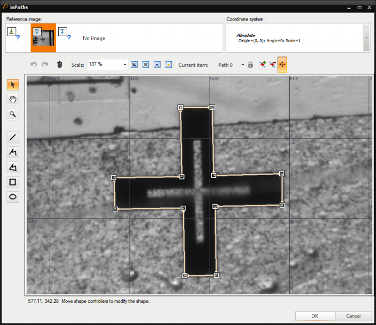
- Now open the path editor by clicking the "..." icon in the inPaths field.
- In the editor, you can choose a reference image from the input set.
- Now draw a closed path in the shape of the marker using a real image as a reference. Close the editor.
- In the filter properties, change the inColor to white.
- Set the Filled parameter of the inDrawingStyle to True.
- Run the program once. Now you should have a black image with a white marker.

-
Now the proper part of detection can begin. Add the LocateSingleObject_Edges1 filter. Open the edge editor by clicking the "..." icon in the inEdgeModel field.
- Mark the area of the marker and set the parameters as shown in the following image.
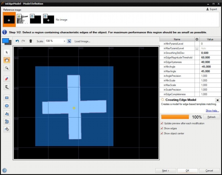
- The angle parameters allow detection of rotated markers. Setting them to -45 and 45 degrees will result in creating models for every rotation in the 90-degree range. Since the marker is symmetrical horizontally and vertically, this range is more than enough. The range may be set to a greater number. However, this would slow down the execution time without noticeable accuracy improvement.
- Mark the area of the marker and set the parameters as shown in the following image.
- To ensure fast and robust execution, you can change appropriate parameters in the filter properties set the parameters.
- Changing the inMinPyramidLevel to 1 speeds up the execution since the required accuracy is lower.
- Set the inEdgeThreshold to 8 so that weaker edges can be detected.
- Set the inEdgePolarityMode to Ignore. This means that the system will seek both object darker than the background and brighter.
- Finally, enter 0.680 into the inMinScore parameter to detect objects that are partially obscured.
- Since the training image is not needed during normal operation, you can disable both the EmptyImage and the DrawPaths_SingleColor filters to speed up the execution.
Macrofilter Main

Used Filters
| Icon | Name | Description |
|---|---|---|
| LocateSingleObject_Edges1 | Detection of an object whose outlines are sharp and rigid. Often one of the first filters in a program. |
Further Readings
- Template Matching - Most detailed description of the Template Matching technique.