
You are here: Start » Machine Vision Guide » Using Local Coordinate Systems
Using Local Coordinate Systems
Introduction
Local coordinate systems provide a convenient means for inspecting objects that may appear at different positions on the input image. Instead of denoting coordinates of geometrical primitives in the absolute coordinate system of the image, local coordinate systems make it possible to use coordinates local to the object being inspected. In an initial step of the program the object is located and a local coordinate system is set accordingly. Other tools can then be configured to work within this coordinate system, and this makes them independent of the object translation, rotation and scale.
Two most important notions here are:
- CoordinateSystem2D – a structure consisting of Origin (Point2D), Angle (real number) and Scale (real number), defining a relative Cartesian coordinate system with its point (0, 0) located at the Origin point of the parent coordinate system (usually an image).
- Alignment – the process of transforming geometrical primitives from a local coordinate system to the coordinates of an image (absolute), or data defining such transformation. An alignment is usually represented with the CoordinateSystem2D data type.
Creating a Local Coordinate System
There are two standard ways of setting a local coordinate system:
- With Template Matching filters it is straightforward as the filters have outObjectAlignment(s) outputs, which provide local coordinate systems of the detected objects.
- With one of the CreateCoordinateSystem filters , which allow for creating local coordinate systems manually at any location, and with any rotation and scale. In most typical scenarios of this kind, the objects are located with 1D Edge Detection, Shape Fitting or Blob Analysis tools.
Using a Local Coordinate System
After a local coordinate system is created it can be used in the subsequent image analysis tools. The high level tools available in Adaptive Vision Studio have an inAlignment (or similar) input, which just needs to be connected to the port of the created local coordinate system. At this point, you should first run the program at least to the point where the coordinate system is computed, and then the geometrical primitives you will be defining on other inputs, will be automatically aligned with the position of the inspected object.
Example 1: Alignment from Template Matching
To use object alignment from a Template Matching filter, you need to connect the Alignment ports:

Template Matching and an aligned circle fitting.
When you execute the template matching filter and enter the editor of the inFittingField input of the FitCircleToEdges filter, you will have the local coordinate system already selected (you can also select it manually) and the primitive you create will have relative coordinates:

Editing an expected circle in a local coordinate system.
During program execution this geometrical primitive will be automatically aligned with the object position. Moreover, you will be able to adjust the input primitive in the context of any input image, because they will be always displayed aligned. Here are example results:
|
|
Example 2: Alignment from Blob Analysis
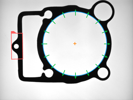
In many applications objects can be located with methods simpler and faster than Template Matching – like 1D Edge Detection, Shape Fitting or Blob Analysis. In the following example we will show how to create a local coordinate system from two blobs:

Two holes clearly define the object location.
In the first step we detect the blobs (see also: Blob Analysis) and their centers:
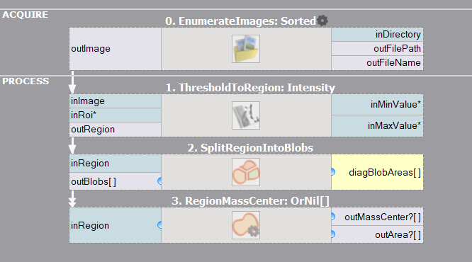
Filters detecting blobs and their centers. |
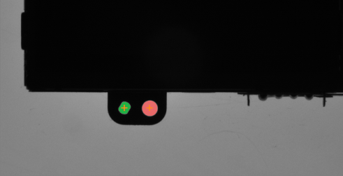
The result of blob detection. |
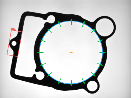
In the second step we sort the centers by the X coordinate and create a coordinate system "from segment" defined by the two points (CreateCoordinateSystemFromSegment). The segment defines both the origin and the orientation. Having this coordinate system ready, we connect it to the inScanPathAlignment input of ScanExactlyNRidges, which will measure the distance between two insets. The measurement will work correctly irrespective of the object position (mind the expanded structure inputs and outputs):
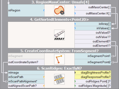
Filters creating a coordinate systems and performing an aligned measurement. |
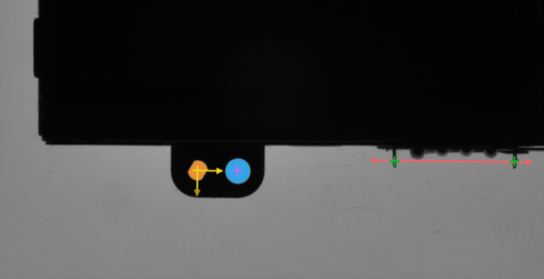
Created local coordinate system and an aligned measurement. |
Manual Alignment
In some cases the filter you will need to use with a local coordinate system will have no appropriate inAlignment input. In such cases the solution is to transform the primitive manually with filters like AlignPoint, AlignCircle, AlignRectangle. These filters accept a geometrical primitive defined in a local coordinate system, and the coordinate system itself, and return the same primitive, but with absolute coordinates, i.e. aligned to the coordinate system of an image.
A very common case is with ports of type Region, which is pixel-precise and, while allowing for creation of arbitrary shapes, cannot be directly transformed. In such cases it is advisable to use the CreateRectangleRegion filter and define the region-of-interest at inRectangle. The filter, having also the inRectangleAlignment input connected, will return a region properly aligned with the related object position. Some ready-made tools, e.g. CheckPresence_Intensity, use this approach internally.
Not Mixing Local Coordinate Systems
It is important to keep in mind that geometrical primitives that appear in different places of a program may belong to different coordinate systems. When such different objects are combined together (e.g. with a filter like SegmentSegmentIntersection) or placed on a single data preview, the results will be meaningless or at least confusing. Thus, only objects belonging to the same coordinate system should be combined. In particular, when placing primitives on a preview on top of an image, only aligned primitives (with absolute coordinates) should be used.
As a general rule, image analysis filters of Adaptive Vision Studio accept primitives in local coordinate systems on inputs, but outputs are always aligned (i.e. in the absolute coordinate system). In particular, many filters that align input primitives internally also have outputs that contain the input primitive transformed to the absolute coordinate system. For example, the ScanSingleEdge filters has a inScanPath input defined in a local coordinate system and a corresponding outAlignedScanPath output defined in the absolute coordinate system:

The ScanSingleEdge filter with a pair of ports: inScanPath and outAlignedScanPath, belonging to different coordinate systems.
| Previous: Template Matching | Next: Optical Character Recognition |