
You are here: Start » Machine Vision Guide » Shape Fitting
Shape Fitting
Introduction
Shape Fitting is a machine vision technique that allows for precise detection of objects whose shapes and rough positions are known in advance. It is most often used in measurement applications for establishing line segments, circles, arcs and paths defining the shape that is to be measured.
As this technique is derived from 1D Edge Detection, its key advantages are similar – including sub-pixel precision and high performance.
Concept
The main idea standing behind Shape Fitting is that a continuous object (such as a circle, an arc or a segment) can be determined using a finite set of points belonging to it. These points are computed by means of appropriate 1D Edge Detection filters and are then combined together into a single higher-level result.
Thus, a single Shape Fitting filter's work consists of the following steps:
- Scan segments preparation – a series of segments is prepared. The number, length and orientations of the segments are computed from the filter's parameters.
- Points extraction – points that should belong to the object being fitted are extracted using (internally) a proper 1D Edge Detection filter (e.g. ScanSingleEdge in FitCircleToEdges) along each of the scan segments as the scan path.
- Object fitting – the final result is computed with the use of a technique that allows fitting an object to a set of points. In this step, a filter from Geometry 2D Fitting is internally used (e.g. FitCircleToPoints in FitCircleToEdges). An exception to the rule is path fitting. No Geometry 2D Fitting filter is needed there, because the found points serve themselves as the output path characteristic points.
 |
 |
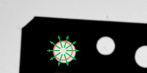
 |
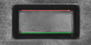
The scan segments are created according to the fitting field and other parameters (e.g. inScanCount). |
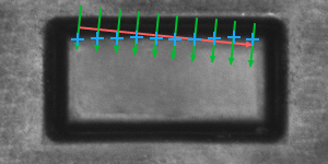
ScanSingleEdge (or another proper 1D Edge Detection filter) is performed. |
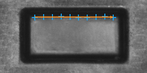
A segment is fitted to the obtained points. |
 |
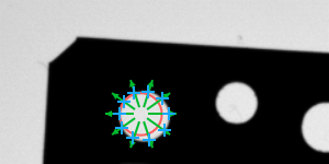 |
 |
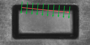
The scan segments are created according to the fitting field and other parameters (e.g. inScanCount). |
ScanSingleEdge (or another proper 1D Edge Detection filter) is performed. |
A segment is fitted to the obtained points. |
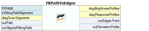
Toolset
The whole toolset for Shape Fitting consists of several filters. The filters differ on the object being fitted (a circle, an arc, a line segment or a path) and the 1D Edge Detection structures extracted along the scan segments (edges, ridges or stripe, all of them clearly discernible on the input image).
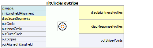 |
 |
Sample Shape Fitting filters.
Parameters
Because of the internal use of 1D Edge Detection filters and Geometry 2D Fitting filters, all parameters known from them are also present in Shape Fitting filters interfaces.
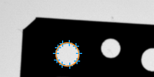
Beside these, there are also a few parameters specific to the subject of shape fitting. The inScanCount parameter controls the number of the scan segments. However, not all of the scans have to succeed in order to regard the whole fitting process as being successful. The inMaxIncompleteness parameter determines what fraction of the scans may fail.
 |
 |
FitCircleToEdges performed on the sample image with inMaxIncompleteness = 0.25. Although two scans have ended in failure, the circle has been fitted successfully.
The path fitting functions have some additional parameters, which help to control the output path shape. These parameters are:
- inMaxDeviationDelta – it defines the maximal allowed difference between deviations of consecutive points of the output path from the corresponding input path points; if the difference between deviations is greater, the point is considered to be not found at all.
- inMaxInterpolationLength – if some of the scans fail or if some of found points are classified to be wrong according to another control parameters (e.g. inMaxDeviationDelta), output path points corresponding to them are interpolated depending on points in their nearest vicinity. No more than inMaxInterpolationLength consecutive points can be interpolated, and if there exists a longer series of points that would have to be interpolated, the fitting is considered to be unsuccessful. The exception to this behavior are points which were not found on both ends of the input path. Those are not part of the result at all.
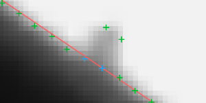 |
FitPathToEdges performed on the sample image with inMaxDeviationDelta = 2 and inMaxInterpolationLength = 3. Blue points are the points that were interpolated. If inMaxInterpolationLength value was less than 2, the fitting would have failed.
| Previous: 1D Edge Detection – Subpixel Precision | Next: Template Matching |