
You are here: Start » Program Examples » Rubber Ring (Advanced)
Rubber Ring (Advanced)
Aim:
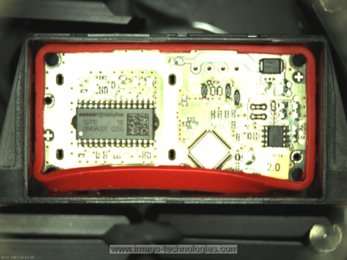
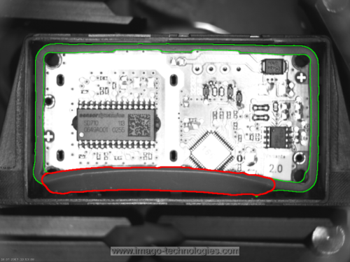
The aim of the program is to detect improperly assembled segments of a rubber band.
Input:
An image of a chip with an assembled rubber band around it.
Output:
Proper and improper segments of the rubber band.
Hints:
This is another variant of the same example but using more advanced techniques. If you do not feel secure enough, please see the simpler variant here. The effect is just the same, and the solution is more user-friendly, though.
In this example, we use similar techniques to the simpler variant but enriched by additional filters.
Labeling connections is explained in this article.
Solution (AVS):
- In Workspace Explorer, open the workspace Examples, and in the Filmstrip window, select the RubberRing dataset. Drag the Image channel to the ACQUIRE section.
- Add a new Step macrofilter, name it DetectRing, connect the ReadFilmstrip output to it and get inside.
- Add the ThresholdToRegion_Color filter and connect macrofilter's inImage with the inImage.
- Click on the ThresholdToRegion_Color filter and set the inMaxDifference to 20 to increase the maximum difference between the image pixel and reference color.
- Add the CloseRegion filter.
- Connect the outRegion to the inRegion.
- Click on the CloseRegion filter, set the inRadiusX to 10.
- Add the FillRegionHoles filter.
- Connect the outRegion with the inRegion.
- Click on the FillRegionHoles filter and set the inMaxHoleArea to 10000 to avoid filling the area inside the rubber ring.
- Add the OpenRegion filter. Connect the outRegion with the inRegion.
- Connect the outRegion to macrofilters outputs and name it outRingRegion.
- Go back to Main and add a new Step macrofilter, name it GetOuterAndInnerContour. Connect the outRingRegion from a previous macrofilter to it and name it inRingRegion.
- Get inside the macrofilter and add the RegionContours filter.
- Connect inRingRegion with the inRegion.
- Add the ConvertToEquidistantPath filter. Connect the outContours with the inPath.
- Add the GetArrayElements filter of the Path type. Connect the outPath with the inArray.
- Connect the outValue1 and the outValue2 to macrofilter outputs and name them outOuter and outInner respectively.
- Go back to Main and add the PathToPathDistanceProfile filter. Connect the outOuter with the inPath1 and the outInner with the inPath2.
- Add the ClassifyByRange filter of the Segment2D type. Make these changes:
- Connect the outConnectingSegments with the inArray.
- Connect the outDistances with the inValues.
- Click on the ClassifyByRange filter and, in Properties window:
- Add a new Step macrofilter, name it DrawDefects and:
- Connect the ReadFilmstrip output to it and name it inImage.
- Connect the outRingRegion from the DetectRegion macrofilter to it and name it inRingRegion.
- Connect the outHigher to it and name it inErrors.
- Get inside the macrofilter and add the ReverseArray filter.
- Right-click on the inErrors, find the Property outputs and select Point1 and Point2.
- Connect the inErrors.Point1 with the inArray.
- Add the JoinArrays filter and connect the inErrors.Point2 with the inArray1. Connect the outArray with the inArray2.
- Add the MakePath filter.
- Connect the outJoinedArray with the inPoints.
- Click on the MakePath filter and set the inClosed to True.
- Add the AverageChannels filter. Connect macrofilter's inImage with the inImage.
- Add the RegionContours filter.
- Connect macrofilter's inRingRegion with the inRegion.
- Click on the RegionContours filter and set the inContourMode to PixelEdges.
- Add the DrawPaths_SingleColor filter.
- Connect the outImage with the inImage.
- Connect the outContours from the RegionContours filter and connect to the inPaths.
- Set the inColor to green.
- Add another DrawPaths_SingleColor filter.
- Connect the outImage from a previous filter with the inImage of the current one.
- Connect the outPath with the inPaths.
- Set the inDrawingStyle.Thickness to 5.
- Set the inDrawingStyle.PointSize to 2.
- Connect the outImage to macrofilter outputs and name it outImage.
Macrofilter Main

Macrofilter DetectRing

Macrofilter GetOuterAndInnerContour

Macrofilter DrawDefects

Used Filters
| Icon | Name | Description |
|---|---|---|
| AverageChannels | Creates a monochromatic image by averaging the input image channels. | |
| ClassifyByRange | E.g. selection of the objects (e.g. blobs) whose associated values (e.g. area) meet the specified minimum and maximum requirements. | |
| CloseRegion | Filling-in small gaps in a region without making it thicker. | |
| ConvertToEquidistantPath | Creates a new path whose characteristic points lie on the input path, but are equally spaced. | |
| DrawPaths_SingleColor | Draws paths on an image with a single color. | |
| FillRegionHoles | Adds pixels to the input region so that it contains no holes. | |
| GetArrayElements | Extracts up to 8 individual elements from an array. | |
| JoinArrays | Concatenates the input arrays one after another. | |
| MakePath | Creates a path structure. | |
| OpenRegion | Removing small parts from a region without making it thinner. | |
| PathToPathDistanceProfile | Computes the profile of distances between two paths. | |
| RegionContours | Computes an array of closed paths corresponding to the contours of the input region. | |
| ReverseArray | Creates an array of the input array elements in reversed order. | |
| ThresholdToRegion_Color | Color analysis with a given reference color. |
Further Readings
- Array - Link to all operations based on arrays in Aurora Vision Studio.
- Blob Analysis - Article presents detailed information about the Blob Analysis technique.