
You are here: Start » Application Notes » Interfacing Hilscher card (Profinet) to Aurora Vision Studio
Interfacing Hilscher card (Profinet) to Aurora Vision Studio
Purpose and equipment
This document explains how to configure Profinet PLC with Aurora Vision Studio using Hilscher Profinet card.
Required equipment:
- Supported Hilscher Profinet PC card
- Aurora Vision Studio 4.12 or later
Hardware connection
All devices must work in a common LAN network, hereinafter called the shared network. In most cases they are connected to each other through a network switch.
The devices shall be connected as follows:
- Master device (e.g. PLC) to the shared network
- Hilscher card to PC
- Hilscher card to the shared network
- PC's network card to shared network
Before proceeding to the further point, make sure that all devices are powered up.
Configuring Hilscher Devices
Be sure to have the newest version of the following drivers:
- Windows driver (recommended 1.5.0.0): download link (for CIFX 50E-RE download V2.x version)
- SYCON.net for configuring slots, generating configuration files: download link
- List of the Profinet firmware (recommended 4.x version, tested 4.7.0.1) download link
A computer restart is highly recommended after driver installations.
Make sure you have the recommended driver installed, newest SYCON.net, and firmware prepared. Profinet requirements are written down in Hilscher_Channel_Open_Profinet documentation.
1) Configuration using cifX Driver Setup Software
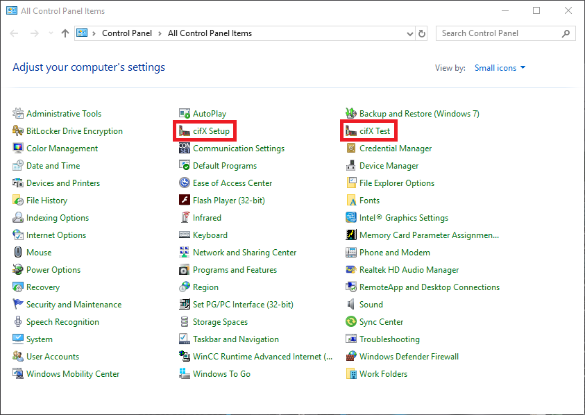
The easiest way to install the firmware to the cifX Driver is using the cifX Driver Setup Software. You can find tools for this software for instance using Control Panel menu as in the picture below.
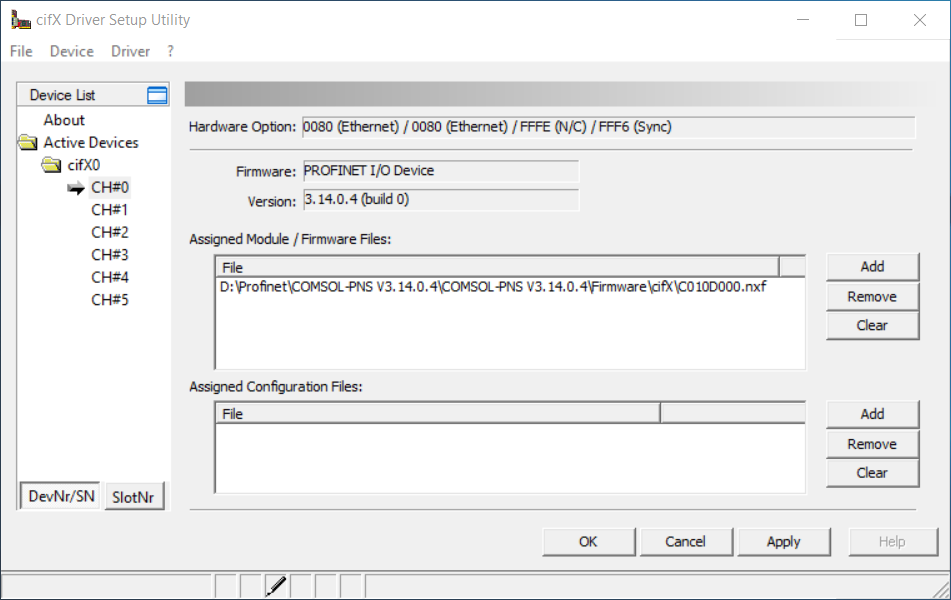
Using cifX Setup application select the channel you would like to configure (usually channel - CH#0) and remove preexisting firmware by clicking "Clear". Then click "Add" to add a new firmware file and navigate to the downloaded Profinet Adapter firmware (path \COMSOL-PNS V3.14.0.4\Firmware\cifX). Then click "Apply" and finish configuration with "OK".
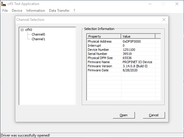
To be sure that firmware is installed properly you can open cifX Test software and then navigate to Device -> Open to achieve the result like below.
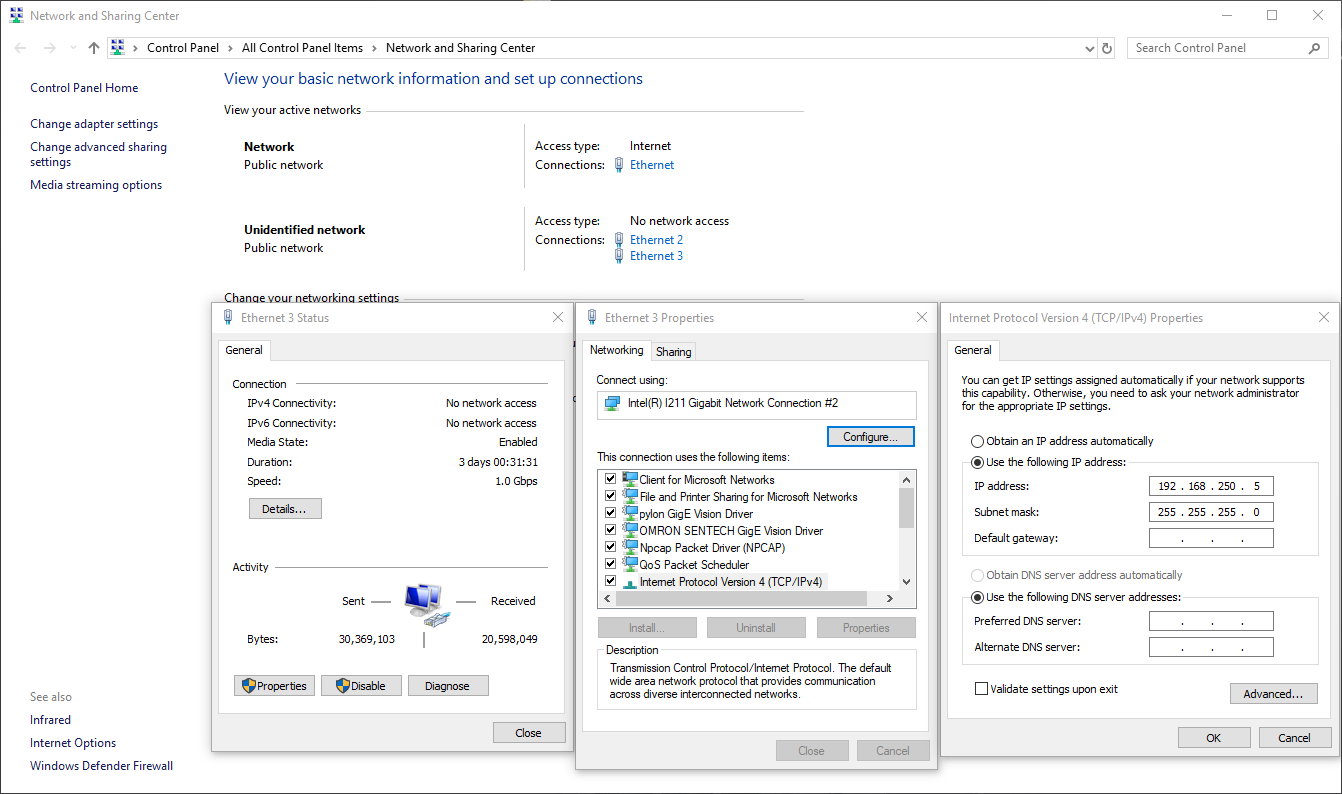
2) Configuration of the network card
It might be necessary to change the IP of the network card from dynamic to static. In this tutorial the following settings are used.
3) Configuration using SYCON.net
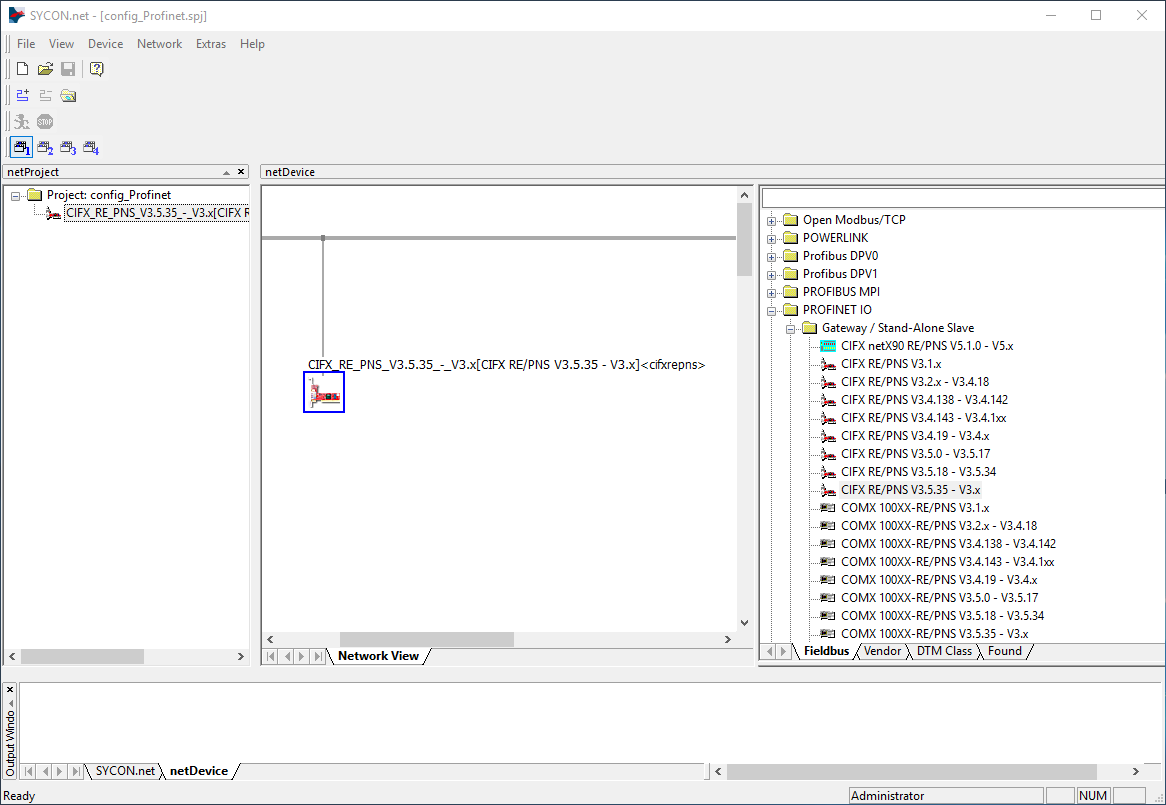
Configuration files are generated in SYCON.net software. Firstly, pick a proper device and drag it to the gray bus on the "Network View". This device you can find navigating to "PROFINET IO -> Gateway / Stand - Alone Slave -> CIFX RE/PNS V3.5.35. - V3.x".
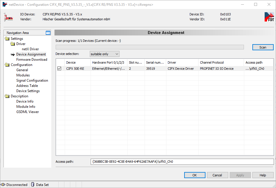
To open the configuration card double click on dropped icon and in the popped-up menu navigate to "Settings/Device Assignment". Then scan for devices by clicking "Scan", mark found one it with a tick like on the image below and then click "Apply".
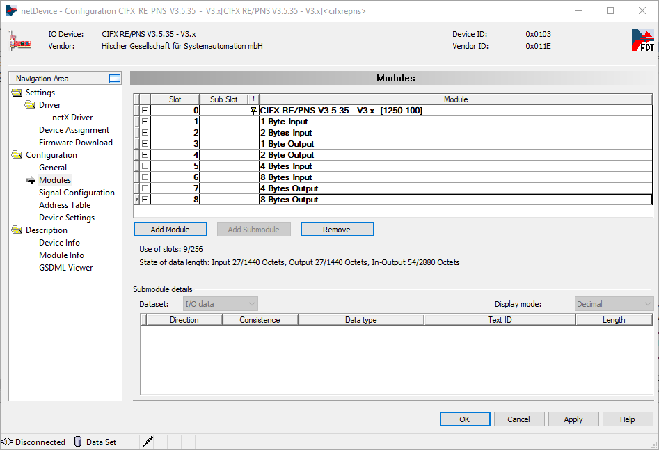
To open card configuration, double click on its icon and select the "Configuration/Modules" category in the Navigation Area on the left side of the dialog. In the main window you can add individual modules. Remember that in Profinet, Slot configuration must match the configuration from your master device, otherwise the connection will not work. For boolean indicators we recommend "1 Byte Output" or "1 Byte Input".
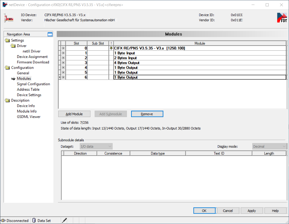
Confirm all changes by clicking "Apply" and then click "OK".
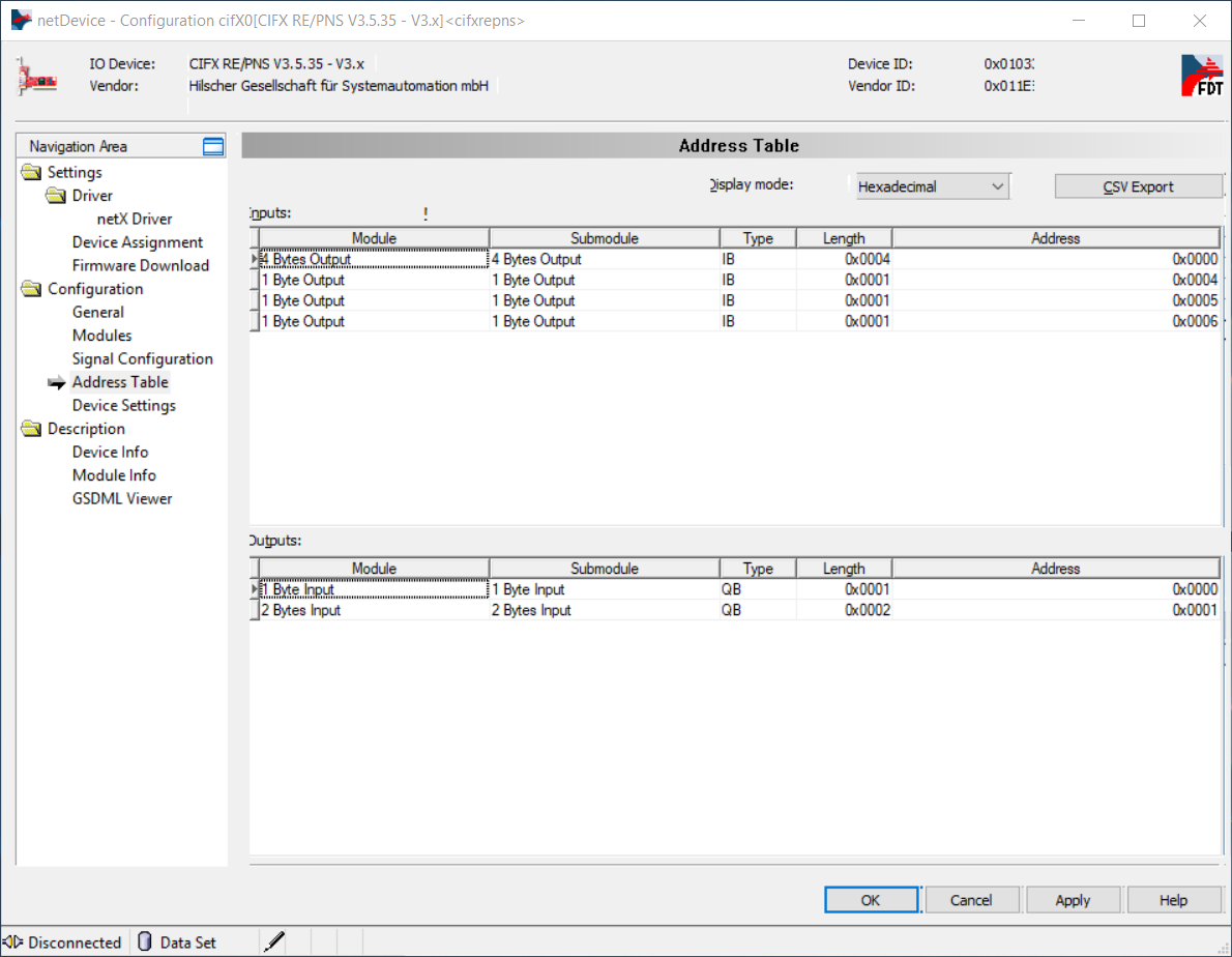
You can see the final address table (addresses on the Hilscher device where input or output data will be available) in the "Configuration/Address table" category. If you plan to use IORead and IOWrite filters, for example Hilscher_Channel_IORead_SInt8, note the addresses. You can switch the display mode to decimal, as Aurora Vision Studio accepts decimal addressing, not hexadecimal. Aurora Vision Studio implementation of Profinet checks whether the address and data size match. In the sample configuration below, writing a byte to address 0x002 would not work, because that module address starts at 0x001 and spans 2 bytes. Moreover, Aurora Vision Studio prohibits writing with a SlotWrite filter to input areas and reading with a SlotRead filter from output areas. Click "OK" when you have finished the proper configuration.
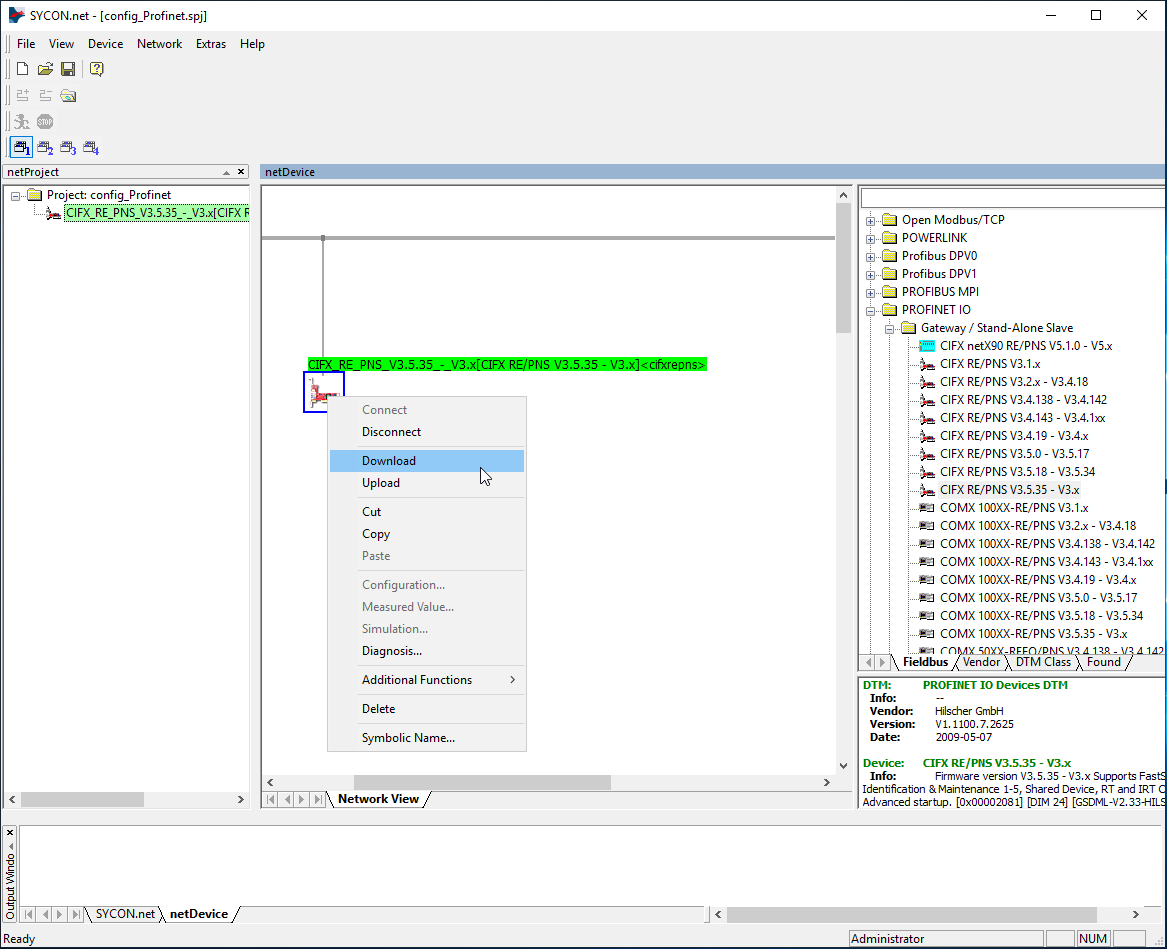
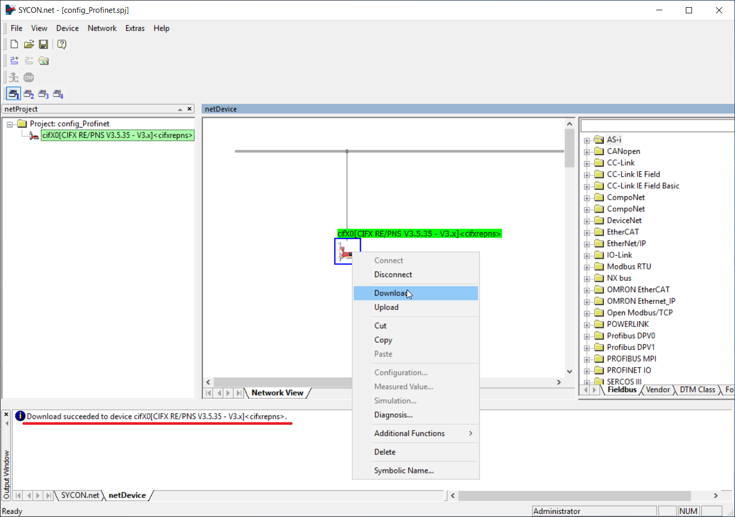
Then you have to download the configuration to the device like on the screen below.
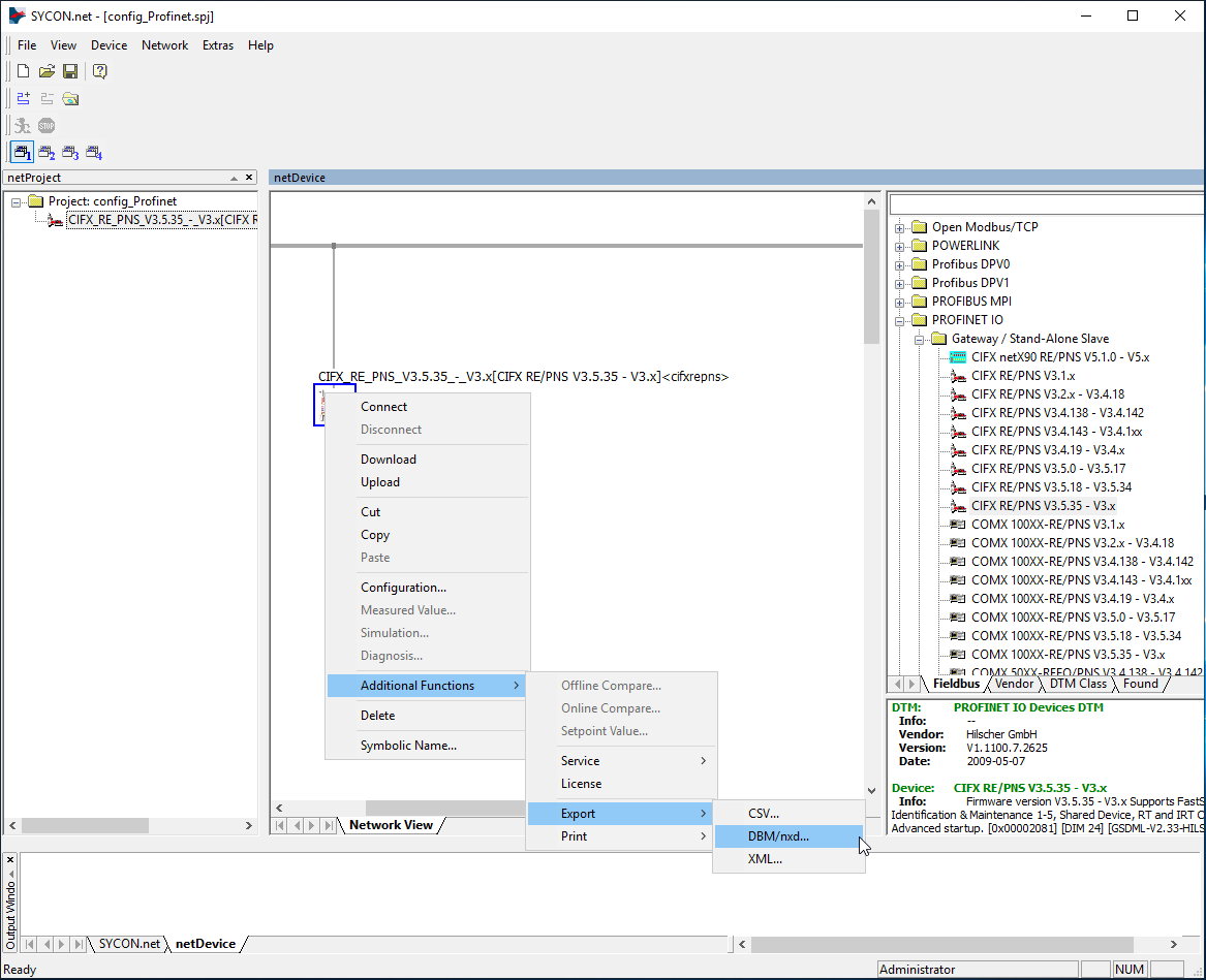
The final step is to generate configuration files for Aurora Vision Studio. You can do this by right-clicking on the device icon, then navigating to "Additional Functions -> Export -> DBM/nxd..", entering your configuration name and clicking "Save". You can now close SYCON.net for this example, remember to save your project before, so that it is easier to add new slots.
4) Working with Profinet in Aurora Vision Studio
The full list of filters for communication over Hilscher devices is available under this link
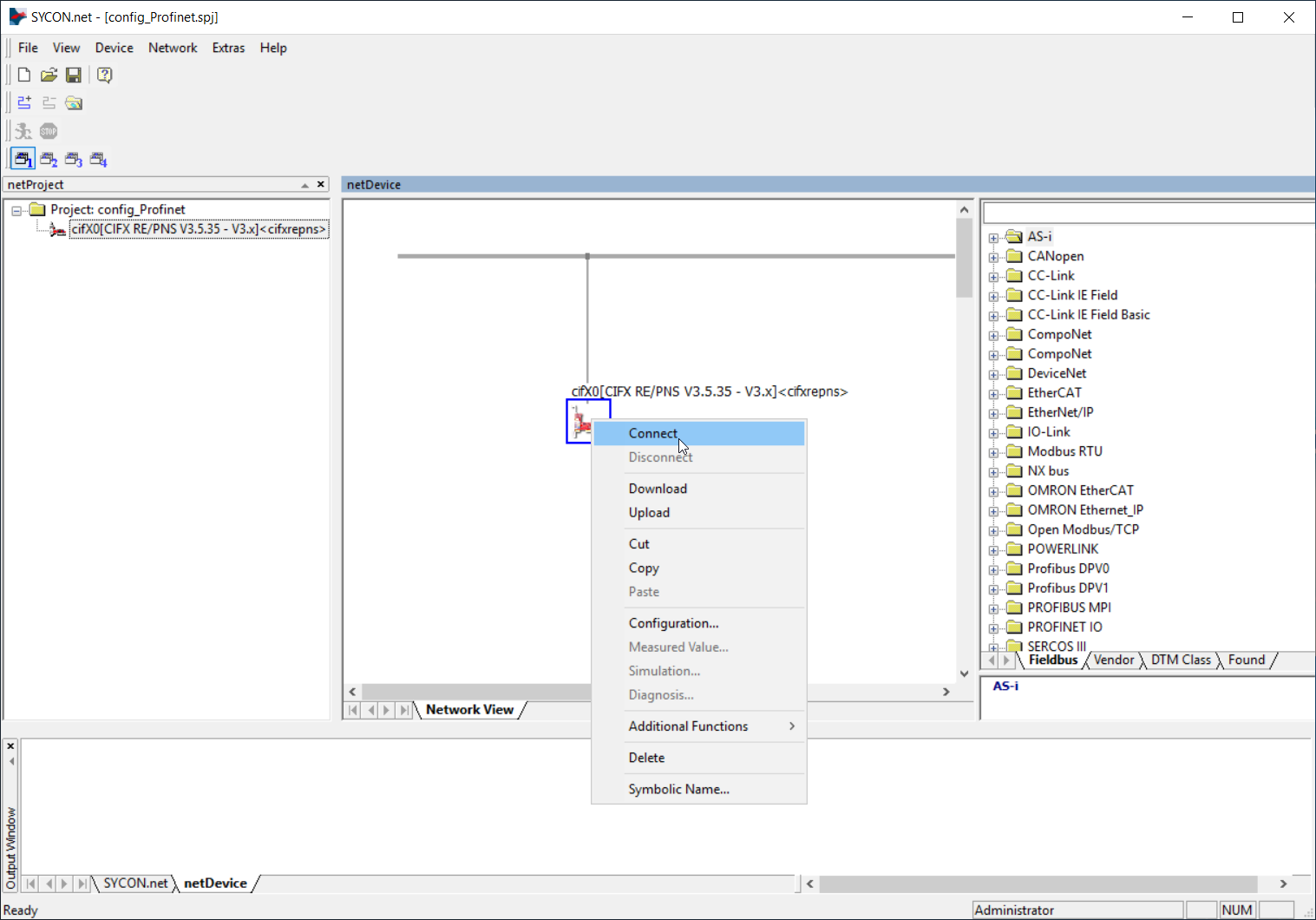
.Before proceeding to the further steps, please check Hilscher and AVS connection using Hilscher_Driver_GetBoardInformation filter. If all previous steps are done correctly you will be able to get device board information including BoardName and ID. Please note that in this step the connection with the Hilscher card via Sycon.net is required, so you need to run the software, right-click on the card icon and click Connect.
As described in previous chapter the Sycon.net application is not required for a proper operation. On the contrary, it is highly recommended to keep it closed and use the generated configuration files to guarantee high stability of the connection.
After following the instruction from chapter 3, you have a xxx.nxd and xxx_nwid.nxd files. To send data over Profinet, follow the below steps:
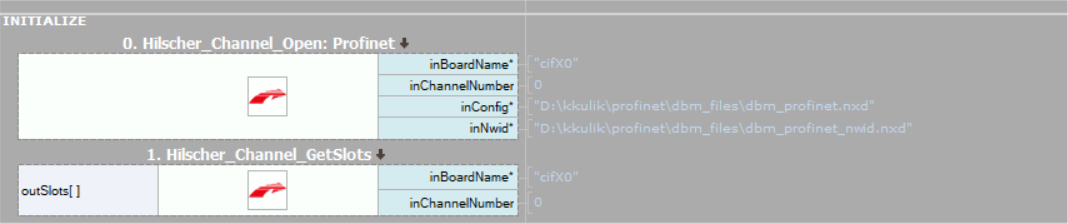
- Configure connection in AVS with Hilscher_Channel_Open_Profinet filter. Drag it from Program I/O category in the Toolbox and drop it in the Program Editor.
- In inBoardName input enter value acquired from Hilscher_Driver_GetBoardInformation filter. In inConfig and inNwid inputs enter paths to generated files from Sycon.net.
- To prevent from I/O errors make sure that you open connection in the initialization step with Hilscher_Channel_Open_Profinet and close it at the end of the program using Hilscher_Channel_Close filter.
- For IO, we recommend SlotRead and SlotWrite filters, as they are more convenient. For example, the Hilscher_Channel_SlotWrite_SInt8 filter writes 8 bytes of signed data to the selected slot. Slot numbers match those in the "Configuration/Modules" category of card configuration in SYCON.net program.
5) Example Configuration
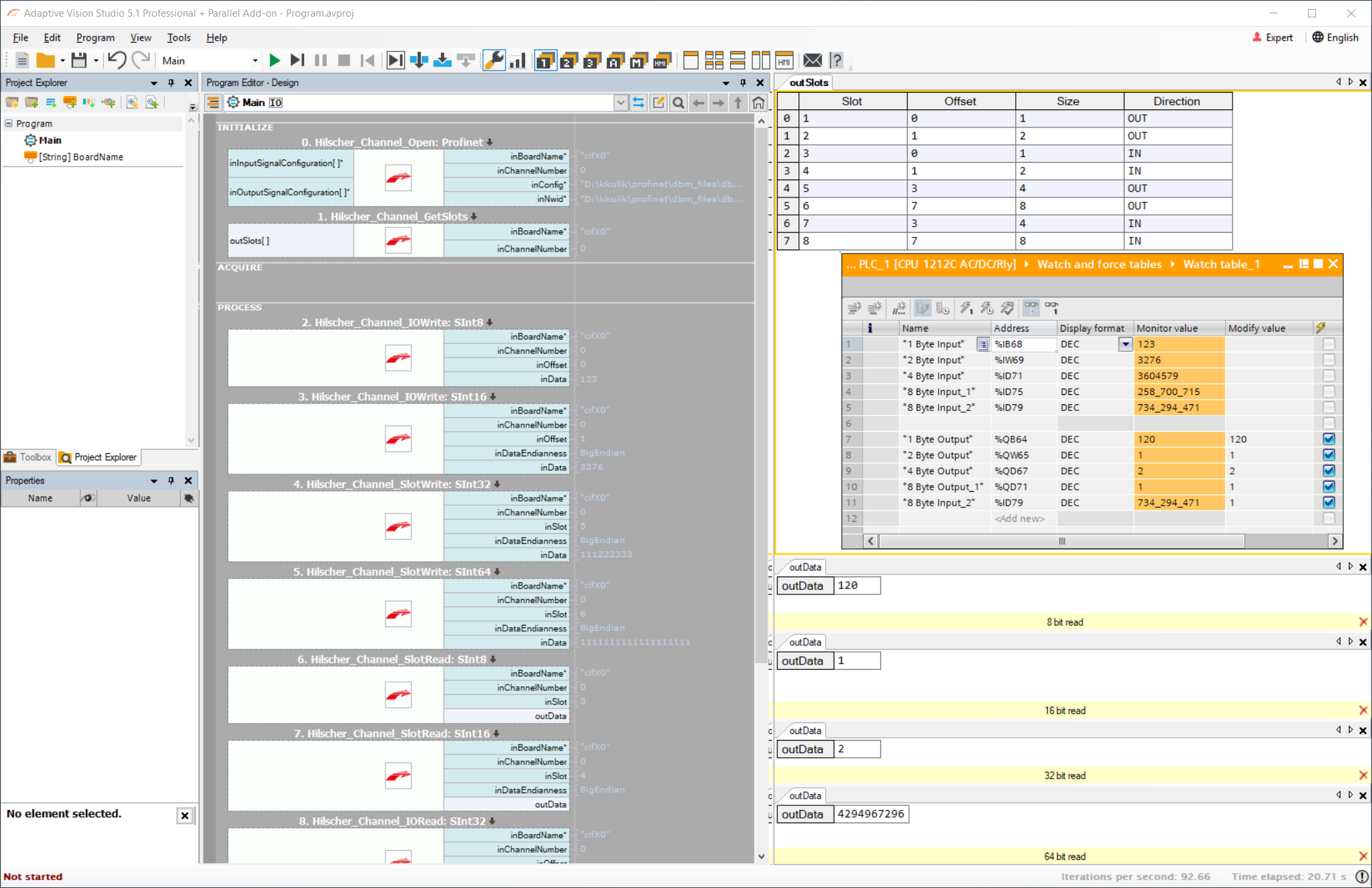
Below you will find an sample configuration of Siemens TIA Portal, Hilscher Sycon and Aurora Vision Studio.
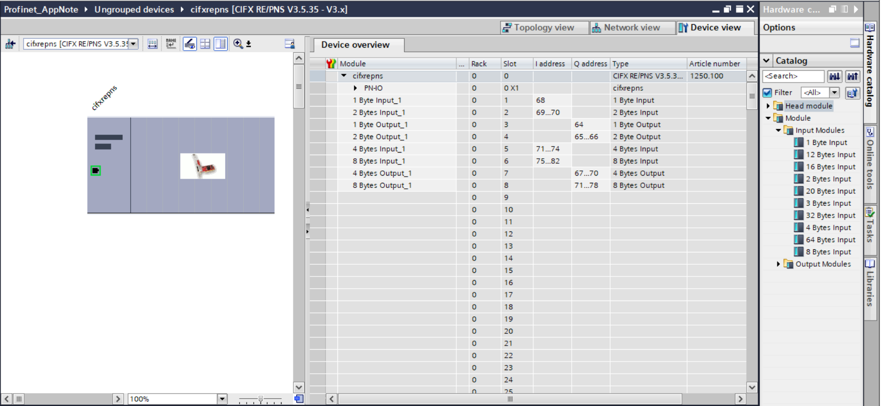
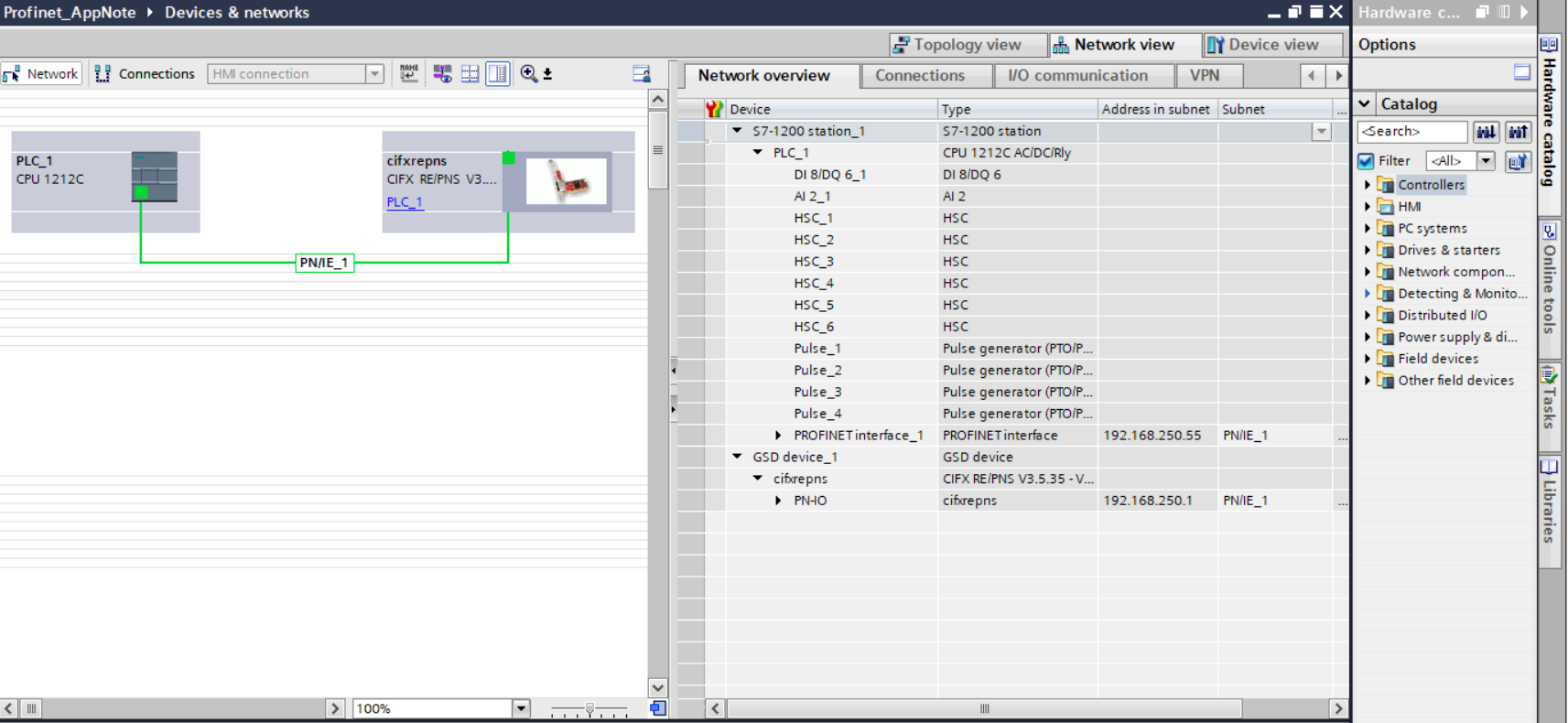
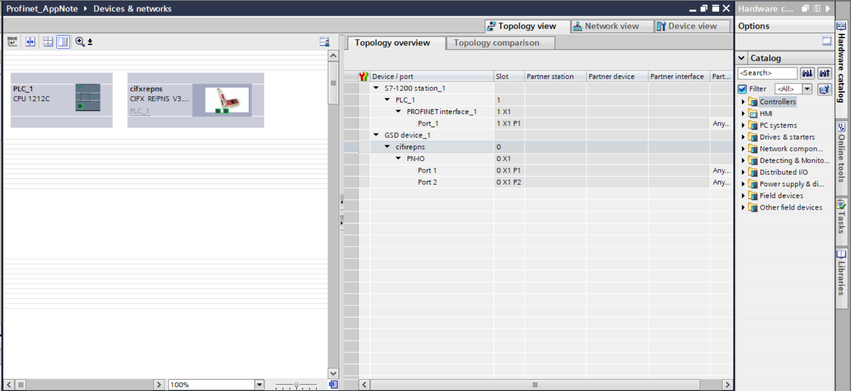
As you can see on the screenshots above the slots are common for each software. The only difference is that Siemens and Hilscher inputs corresponds to outputs from Aurora Vision Studio and vice-versa - Siemens output is Aurora Vision Studio input. It should be considered in the following manner: data outgoing from PLC (output) is incoming to Aurora Vision Studio (input) while data incoming to PLC (input) is outgoing from Aurora Vision Studio (output).
The summarization of data type and directions you will find in the table below:
| TIA Portal | Sycon | Aurora Vision Studio | |||
|---|---|---|---|---|---|
| Size | Type | Size | Type | Size | Type |
| 1 Byte | Input | 1 Byte | Input | SInt8 | Output |
| 2 Bytes | Input | 2 Bytes | Input | SInt16 | Output |
| 4 Bytes | Input | 4 Bytes | Input | SInt32 | Output |
| 8 Bytes | Input | 8 Bytes | Input | SInt64 | Output |
| 1 Byte | Output | 1 Byte | Output | SInt8 | Input |
| 2 Bytes | Output | 2 Bytes | Output | SInt16 | Input |
| 4 Bytes | Output | 4 Bytes | Output | SInt32 | Input |
| 8 Bytes | Output | 8 Bytes | Output | SInt64 | Input |
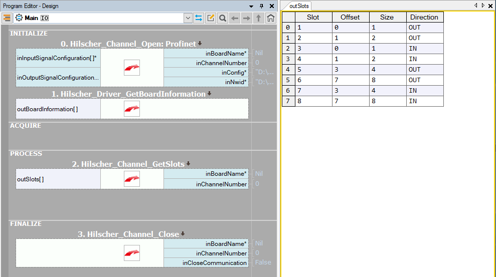
For the slot configuration described in this paragraph the Aurora Vision Studio program will look as follows:
You can use both Hilscher_Channel_IOWrite / Hilscher_Channel_IORead or Hilscher_Channel_SlotWrite / Hilscher_Channel_ SlotRead to send and receive data. The only difference is in addressing the accessible data:
- IORead and IOWrite filters use the offset value
- SlotRead and SlotWrite filters use the slot numbers
Both of the information you will find in output outSlots from Hilscher_Channel_GetSlots filter.
Sometimes it is necessary to combine few integer values into one slot of data. In order to accomplish this task you can use binary buffers in Aurora Vision Studio. Let's assume that someone would like to write two 2-bytes integers into one 4 bytes slot (SInt32 in Aurora Vision Studio). In this situation the program should look as follows:
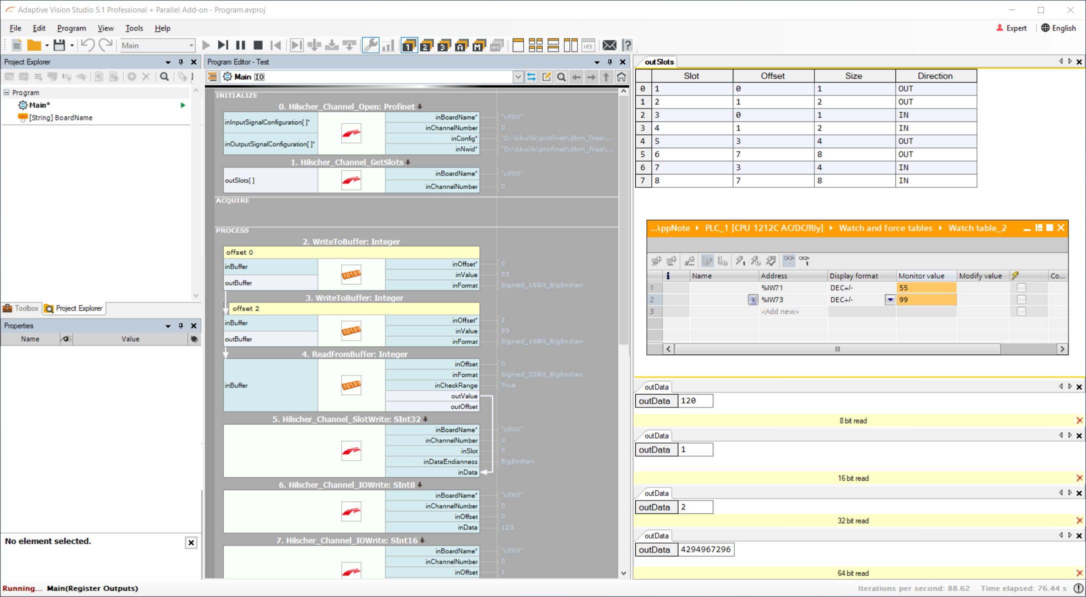
First we use two WriteIntegerToBuffer filters with specified format: Signed_16Bit_BigEndian connected in cascade to write two different values into one buffer (in this case 55 and 99). Also we specify the offset where the second value should be written. Later we extract the combined value as one Integer with filter ReadIntegerFromBuffer. For 8 bytes integers should be used ReadLongFromBuffer. Here we also specify the format of data (Signed_32Bit_BigEndian). Later we send the obtained number with Hilscher_Channel_SlotWrite_SInt32. Between ReadFromBuffer and SlotWrite the data is meaningless but later in TIA Portal when we access it as two separate 2-bytes values we get the send values.
Troubleshooting
If it is still not possible to use AVS with Hilscher card first, make sure that you done correctly all previous steps and then use following advices.
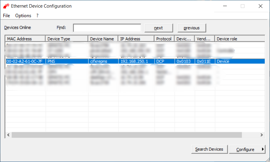
- Use Ethernet Device Configuration software to set static IP address to Hilscher card.
- Make sure that the current program setting is loaded to the Hilscher card. If not, please use the SYCON.net application to connect and download settings to the devices, as shown in the picture below.
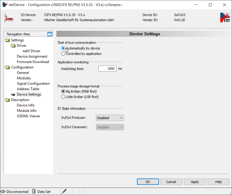
- If your master device has problem with connection with Hilscher card use following settings using Sycon.net application. In order to do this right-click on the card icon and select Configuration...
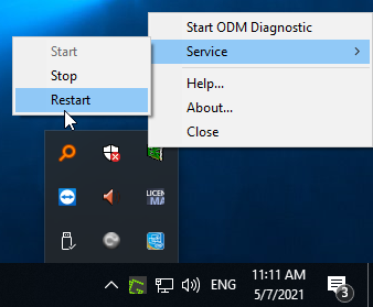
- After changes it may be necessary to restart ODMV3 service.
- If none of the above advice has helped, please restart your computer.