
You are here: Start » User Interface » Connecting and Configuring Filters
Connecting and Configuring Filters
After a filter is added to the program it has to be configured. This consists in setting its inputs to appropriate constant values in the Properties window or connecting them with outputs of other filters. It is also possible to make an input linked with an external AVDATA file, connected with HMI elements or with Global Parameters.
Connecting with Other Filters
Filters receive data from other filters through connections. To create a connection, drag an output of a filter to an input of a filter located below in the Program Editor (upward connections are not allowed). When you drag an output - possible destinations will be highlighted. It is basic way to create program's work-flow.
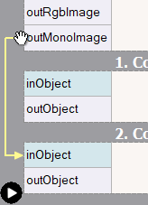
For convenience, new connections can also be created by forking existing connections (drag from the vertical part of the existing connection):
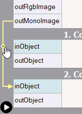
Moreover, it is possible to reconnect an existing connection to another output or input port by dragging the connection's head (near the destination port) or the connection's first horizontal segment (near the source port).
Another way to create connections between filters is by using only the Properties window.
When you click the plug ( ) icon in the right-most column, you get a list with possible connections for this input.
When the input is already connected the plug icon is solid and you can change the connection to another one.
) icon in the right-most column, you get a list with possible connections for this input.
When the input is already connected the plug icon is solid and you can change the connection to another one.
Setting Basic Properties
Most of the filters have several parameters which you can set in the Properties window as shown on the picture below. It is very important to go through these parameters is order to get desired results for your specific application. To start, first select a filter in the Program Editor window.
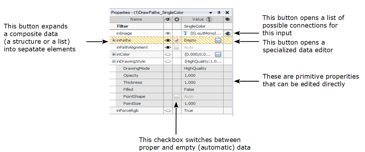
Note: After clicking on the header of the properties table it is possible to choose additional columns.
Editing Geometrical Primitives
To edit geometrical data, such as line segments, circle, paths or regions, click the three dots button (
 ) in the Properties window at the input port
you want to set or modify. A window similar to the one below will appear. The first thing you will
usually need to do, when you open this window for the first time, is to select the background image
from the list at the top of the window. This will set a context for your geometric data.
) in the Properties window at the input port
you want to set or modify. A window similar to the one below will appear. The first thing you will
usually need to do, when you open this window for the first time, is to select the background image
from the list at the top of the window. This will set a context for your geometric data.
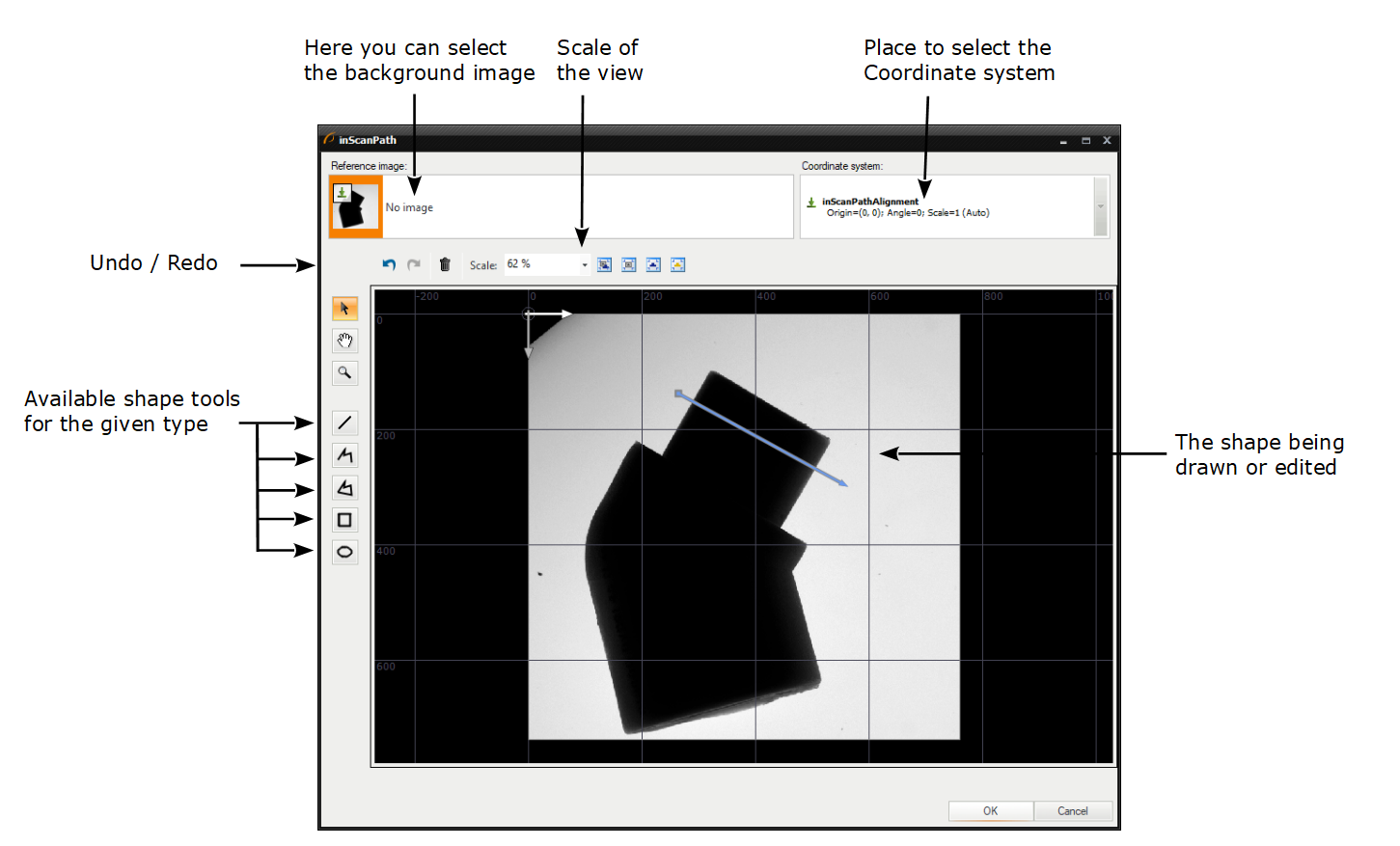
Editing of a path in a context of an image.
Tips:
- Select a point and use its context menu to inspect or set the numeric coordinates.
- Use the mouse wheel to zoom the view without changing the tool.
- Hold 3rd mouse button and drag to move the view without changing the tool.
- Hold Ctrl to limit the segment angles to the multitudes of 15 degrees.
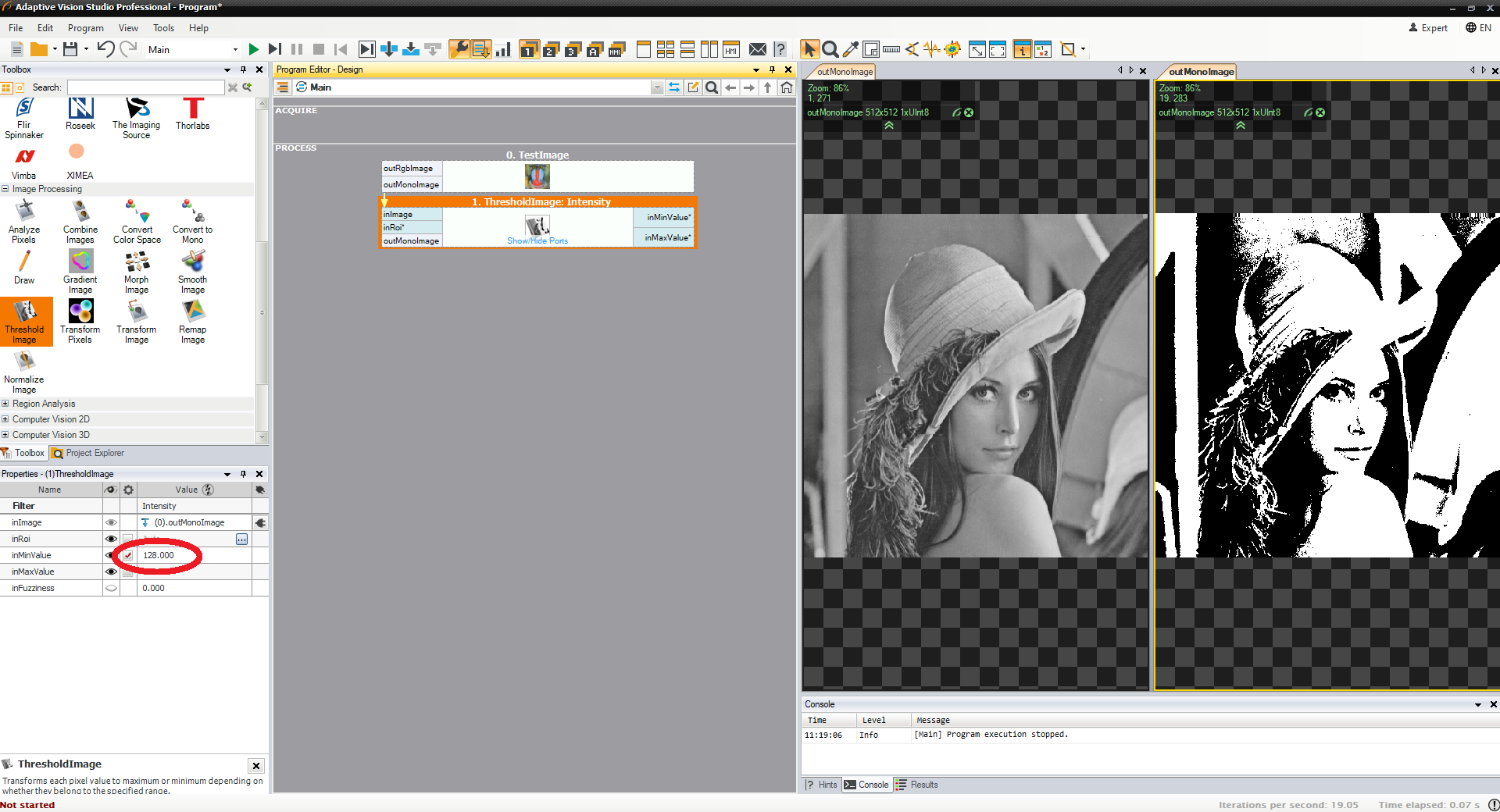
Testing Parameters in Real Time
One of the greatest features of Adaptive Vision Studio is its orientation on rapid development of algorithms. This encompasses the ability to instantly see how different values of parameters affect the results. Due to the dynamic nature of this feature it cannot be presented in a static picture, so please follow the instructions:
- Create a simple program with a TestImage filter connected to a ThresholdImage filter.
- Put the output of the ThresholdImage to a data preview.
- Click Iterate Current Macro
 to execute the program to the last filter, but without ending it as the whole (the execution state will be: Paused).
 - Select the ThresholdImage filter in the Program Editor and change its inMinValue input in the Properties window.
Now, you will be able to see in real time how changing the value affects the result.
Re-executing a filter after a change of a parameter.
Remarks:
- Please note, that although being extremely useful, this is a "dirty" feature and may sometimes lead to inconsistencies in the program state. In case of problems, stop the program and run it again.
- This feature works only when the filter has already been executed and the program is Paused, but NOT Stopped.
- By default re-executed is the entire macrofilter. By unchecking the "Global Rerun Mode" setting the re-execution can be limited to a single filter. This can be useful when there are long-lasting computations in the current macrofilter.
- It is not possible to re-execute i/o filters, loop accumulators or loop generators (because this would lead to undesirable side effects). These filters are skipped when the entire macrofilter is getting re-executed.
- When re-executing a nested instance of another macrofilter, the previews of its internal data are NOT updated.
- Re-executing some filters, especially macrofilters, can take much time. Use the Stop command (Shift+F5) to break it, when necessary.
- If you set an improper value and cause a Domain Error, the program will stop and it will have to be started again to use the re-execution feature.
- The filter parameters can also be modified during continuous program execution (F5).
Linking or Loading Data From a File
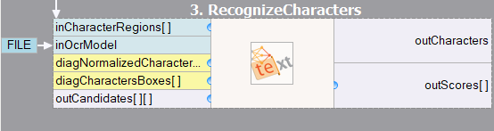
Sometimes data values that have to be used on an input of a filter are stored in an .avdata file, that has been created as a result of some Adaptive Vision Studio program (for example creating a custom OCR model). It is possible to load such data to the program with the LoadObject filter, but most often it is more convenient and more effective to link the input port directly to the file. To create such a link choose Link from AVDATA File... from the context menu of the input (click with the right mouse button on an input port of a filter).
Input data linked from an AVDATA file.
It is also possible to load, not link, data from an .avdata file. This is done with the Import from AVDATA File... command in the context menu, which copies the data and makes them part of the current project.
Connecting HMI and Global Parameters
It is also possible to connect filter inputs from outputs of HMI elements and from Global Parameters. Both get displayed as rectangular labels at the sides of the Program Editor as can be seen on the image below:
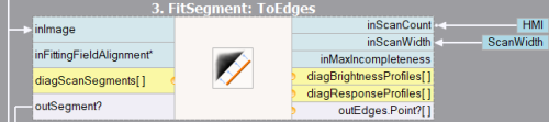
A filter with connections from HMI and from a Global Parameter.
For further details please refer to the documentation on the specific topics:
Writable and Readable Global Parameters
It is possible to read and write the value of global parameter by using ReadParameter and WriteParameter filters. This approach allows users to change global parameter values accordingly to their needs at any point of an algorithm. A few practical applications of this feature are listed below:
- Managing recipes depending on a signal from PLC,
- Storing data transferred between nested macrofilters,
- Setting global flags.
Labeling Connections
Connections are easier to follow than variables as long as there are not too many of them. When your program becomes complicated, with many intersecting connections, its readability may become reduced. To solve this problem Adaptive Vision Studio provides a way to replace some connections with labels. You can right-click on a connection, select "Label All Connections..." - when there is more than one connection or "Label Connection..." when only one connection is present. Then set the name of a label that will be displayed instead. The labels are similar to variables known from textual programming languages – they are named and can be more easily followed if the connected filters are far away from each other. Here is an example:
A program with some long connections becomes not easy to analyze. |
Long connections are replaced with labels for better readability. |
Remarks:
- Labeled connections can be brought back (unlabeled) by using the "Un-label This Connection" or "Un-label All Connections" commands available in the context menu of a label.
- Please note, that when your program becomes complicated, the first thing you should consider is reducing its complexity by refactoring the macrofilter hierarchy or rethinking the overall structure. Labeling connections is only a way to visualize the program in a more convenient way and does not make its structure any simpler. It is the user's responsibility to keep it well organized anyway.
- Adaptive Vision Studio enforces that all connections between filters are clearly visualized, even if making them implicit would make programming easier in typical machine vision applications. This stems from our design philosophy that assumes that: (1) it is wrong to hide something that the user has to think about anyway, (2) the user should be able to understand all the details of a macrofilter looking at a static screen image.
- When the amount of connections becomes large despite good program structure you should also consider creating User Structures that may be used for merging multiple connections into one. (Do NOT use global parameters for that purpose).
Invalid Connections
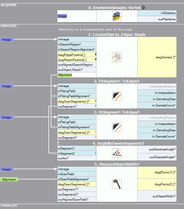
As types of ports in macrofilters and formulas may be changed after connections with other filters
have been created, sometimes an existing connection may become invalid. Such an invalid connection will be
marked with red line and white cross in the Program Editor:
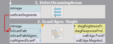 Invalid connections do not allow to run the program. There are two ways to fix it: replace the invalid
connections or revise the types of the connected ports.
Invalid connections do not allow to run the program. There are two ways to fix it: replace the invalid
connections or revise the types of the connected ports.
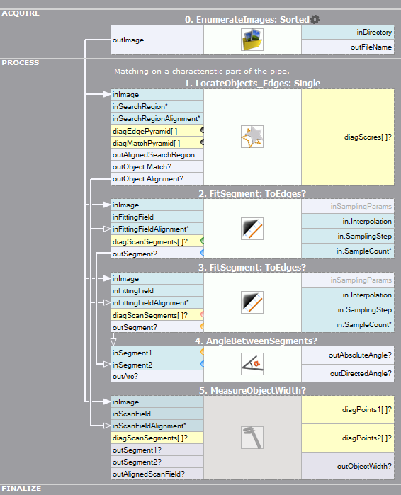
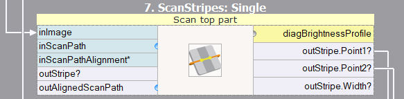
Property Outputs
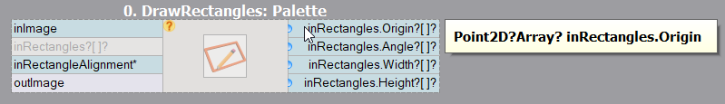
Many types of data can be decomposed into simpler elements called fields or properties. For example, Point2D is a structure composed of "X" and "Y" fields, whereas arrays have a "Count" property informing about the number of contained elements and "IsArrayEmpty" property checking whether there are any. Such properties can be exposed as additional filter outputs (or inputs), so that they will be directly available for creating connections with other filters. Accessing property outputs works also for ports on macrofilter input blocks inside of macrofilters.
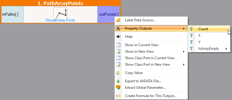
Accessing fields of Point2DArray type.
Not all structure fields are always available. For example the Image type gives access only to information such as: Width, Height, Depth, but not to pixel data. The Count property is available only for output structures, but not for inputs.
Additional Property Outputs
Some of the properties are calculated or derived basing on the current state of the output (for example, checking whether the array is empty or counting its elements), whereas other are derived directly from the internal structure of the type (for example, "X" and "Y" fields composing Point2D structure). The types providing such properties are listed in the table below.
| Structure name | Property outputs |
|---|---|
| Bool | Not |
| ByteBuffer | Size IsByteBufferEmpty |
| Histogram | Size |
| Matrix | IsMatrixEmpty |
| Path |
Size IsPathEmpty Points |
| Profile | Size IsProfileEmpty |
| Region | Area IsRegionEmpty |
| Segment2D | Length |
| String | Length IsStringEmpty |
| Vector2D | Length |
| Vector3D | Length |
There are also special types, which cannot exist independently. They are used for wrapping outputs, which may not be produced under some conditions (Conditional) or optional inputs (Optional), or else for keeping a set of data of specified type (Array). Property outputs of such types are listed in the table below.
| Type name | Property outputs |
|---|---|
| Array | Count IsArrayEmpty |
| ArrayArray (array of arrays) | Count IsArrayEmpty IsNestedArrayEmpty |
| Conditional | IsNil |
| Optional | IsNil |
All of the above-mentioned property outputs are specific for the type. However, ports of Array, Optional or Conditional type may have more property outputs, depending on the wrapped type. For example, if the output of a filter is an array of regions, this port will have Count, IsArrayEmpty (both resulting from the array form of the port), IsRegionEmpty and Area (both resulting from the type of the objects held in the array - in this case, regions) as property outputs. However, if the output of a filter is an array of objects without any property outputs (e.g. Integer), only outputs resulting from the array form of the port (Count and IsArrayEmpty) will be available.
Tip: Avoid using basic filters like Not, ArraySize which will have bigger performance impact than additional property outputs.
Difference between IsNil and IsEmpty
The main difference between these property outputs lie in their impact on the program. Nil value usually means that the object was not detected. Most of the filters, after obtaining Nil value, go into conditional execution mode. It means, that the the filter will be omitted if the input value is Nil. In case of Empty value the rest of the code will be executed, however some of the filter may throw a Domain Error. The tips on how to deal with them are present in our documentation
Expanded Input Structures
Analogously to expanding output properties, it is also possible to expand input structures. This works only for basic structures which allow access to all their fields (e.g. Point2D, but not Image). Please note, that the expanded input structure is replaced by the fields it consists of (unlike by adding property outputs, where the structure itself remains available).
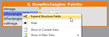
Expanding filter input of Rectangle2D?Array? type.
Result of expanding input of Rectangle2D?Array? type.
Comment Blocks
Comments are very important part of every computer program. They keep it clear and easy to understand during development and further maintenance. There are two ways to make a comment in Adaptive Vision Studio. One way is to add a special comment block. Another option is adding a comment directly in the filter. To add a new comment block to program click the right mouse button on the Program's Editor background and select the "Add Comment Here" option like on the image below.
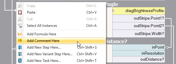
Adding a new comment.
Comment block can be very useful for describing the details of the algorithm.
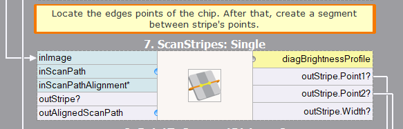
Comments can be used for describing program steps.
But when you need just a simple tip or short remark, use a "Add Comment" after mouse right click on the filter:
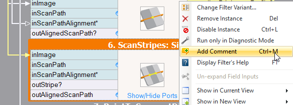
New comment directly in the filter.
| Previous: Finding Filters | Next: Creating Macrofilters |