
You are here: Start » HMI » Designing HMI
Designing HMI
Introduction
Although image analysis algorithms are the central part of any machine vision application, a human-machine interface (HMI, end user's graphical environment) is usually also very important. Adaptive Vision Studio, as a complete software environment, comes with an integrated graphical designer, which makes it possible to create end user's graphical interfaces in a quick and easy way.
|
|
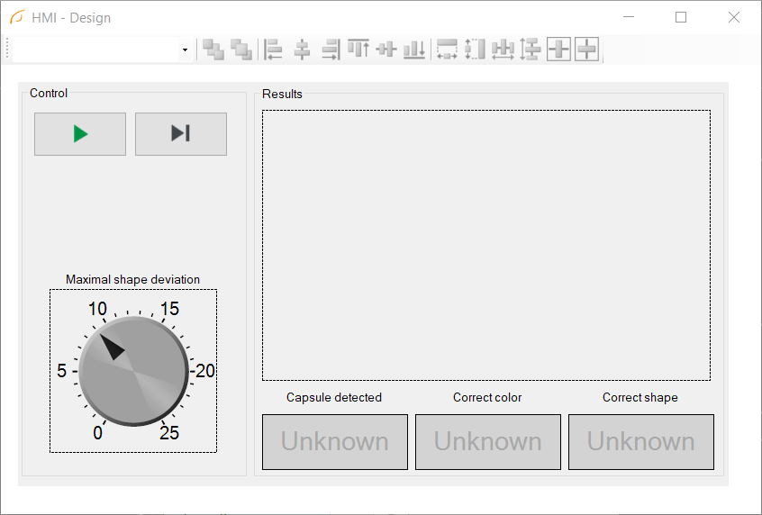
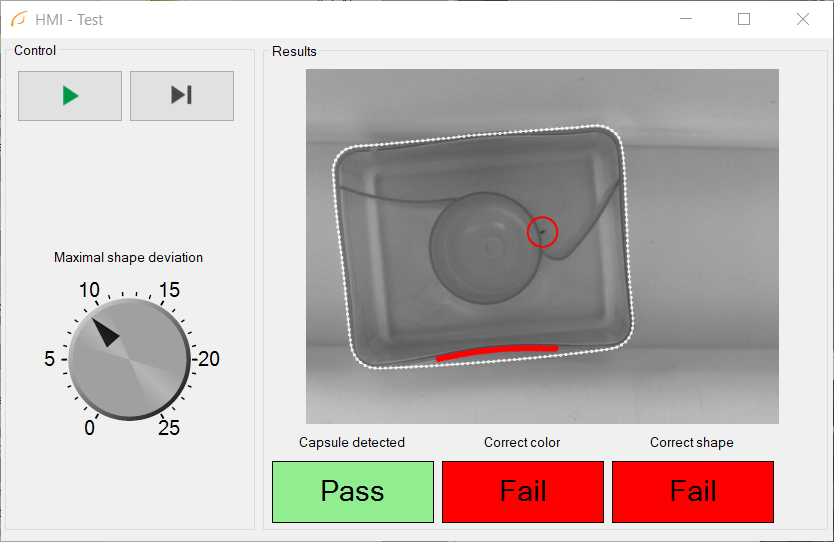
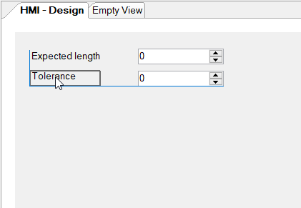
A very simple HMI example: at design time (left) and at run time (right).
The building blocks of a user interface are called controls. These are graphical components such as buttons, check-boxes, image previews or numeric indicators. The user can design a layout of an HMI in an arbitrary way by selecting controls from the HMI Controls window and by placing them on the HMI Canvas. The Properties window will be used to customize such elements as color, font face or displayed text. There are also some controls, called containers, which can contain other controls in a hierarchical way. For example, a TabControl can have several tabs, each of which can contain a different set of other controls. It can be used to build highly sophisticated interfaces.
HMI controls are connected with filters in the standard data-flow way: through input and output ports. There are three possible ways of connecting controls with filters:
- From a filter's output to a control's input – e.g. for displaying an image or a text result.
- From a control's output to a filter's input, as data sources – e.g. for setting various parameters in a program with track-bars or check-boxes.
- From a control's output to a filter's input, as events – e.g. for signaling that a button has been clicked.
There are also a few properties in HMI controls that can be connected directly between two different control. See Label.AutoValueSource and the EnableManager control.
Overview of Capabilities
The HMI Designer in Adaptive Vision Studio is designed for very easy creation of custom user interfaces which resemble physical control panels (a.k.a. front panels). With such an interface the end user will be able to control execution process, set inspection parameters and observe visualization results. There are also more advanced features for protecting the HMI with passwords, saving its state to a file, creating multi-screen interfaces or even for allowing the end user to create object models or measurement primitives.
There is, however, a level of complexity, at which other options of creating end user's graphical interfaces may become suitable. These are:
- Creating custom HMI controls in the C# programming language – especially for dynamic or highly interactive GUI elements, e.g. charts.
- Using .NET Macrofilter Interfaces and then creating entire HMI in the C# programming language.
- Using C++ Code Generator and then creating entire HMI in the C++ programming language.
Note: Adaptive Vision Executor with HMI support is only available on Microsoft Windows operating system. For Linux we recommend generating C++ code and creating the user interface with Qt library.
Adding HMI to a Project
To open HMI Designer choose View » HMI Designer command in the Main Menu
or click the HMI button on the Toolbar:

This adds "HMI - Design" special view (which can be undocked), and a new window, HMI Controls. The Properties window shows parameters of the selected control – here, of the main HMI Canvas.
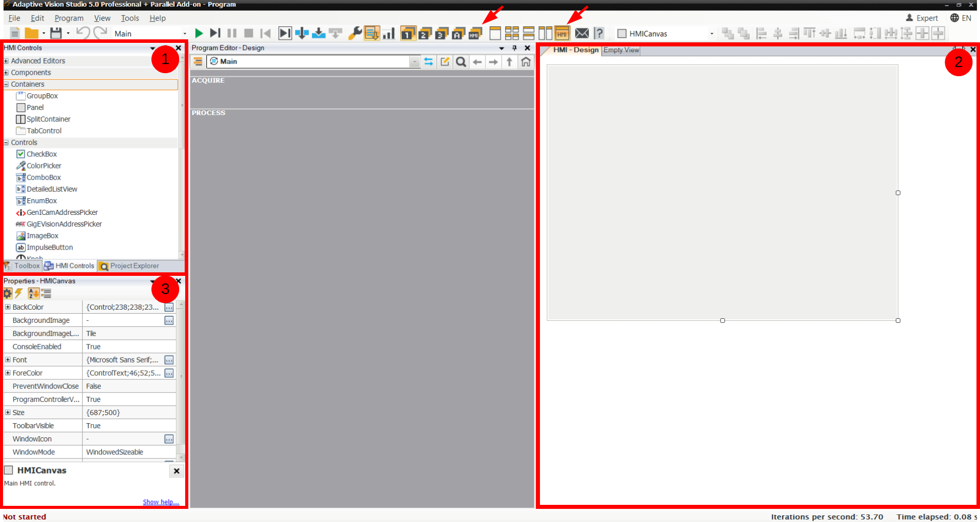
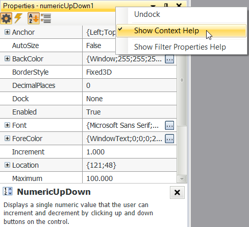
Elements of the HMI Designer: (1) HMI Controls catalog, (2) HMI Editor, (3) Control's Properties + its context-sensitive help.
HMI Canvas is an initial element in the HMI Design view. It represents the entire window of the created application. At the beginning it is empty, but controls will be placed on it throughout HMI construction process.
Removing HMI
If at any point you decide that the created HMI is not needed anymore, it can be removed with a the Edit » Remove HMI command available in the Main Menu.
Basic Workflow
The HMI design process consists in repeating the following three steps:
- Drag & drop a control from HMI Controls to HMI Editor. Set its location and size.
- Set properties of the selected control.
- Drag & drop a connection between the control's input or output with an appropriate filter port in Program Editor.
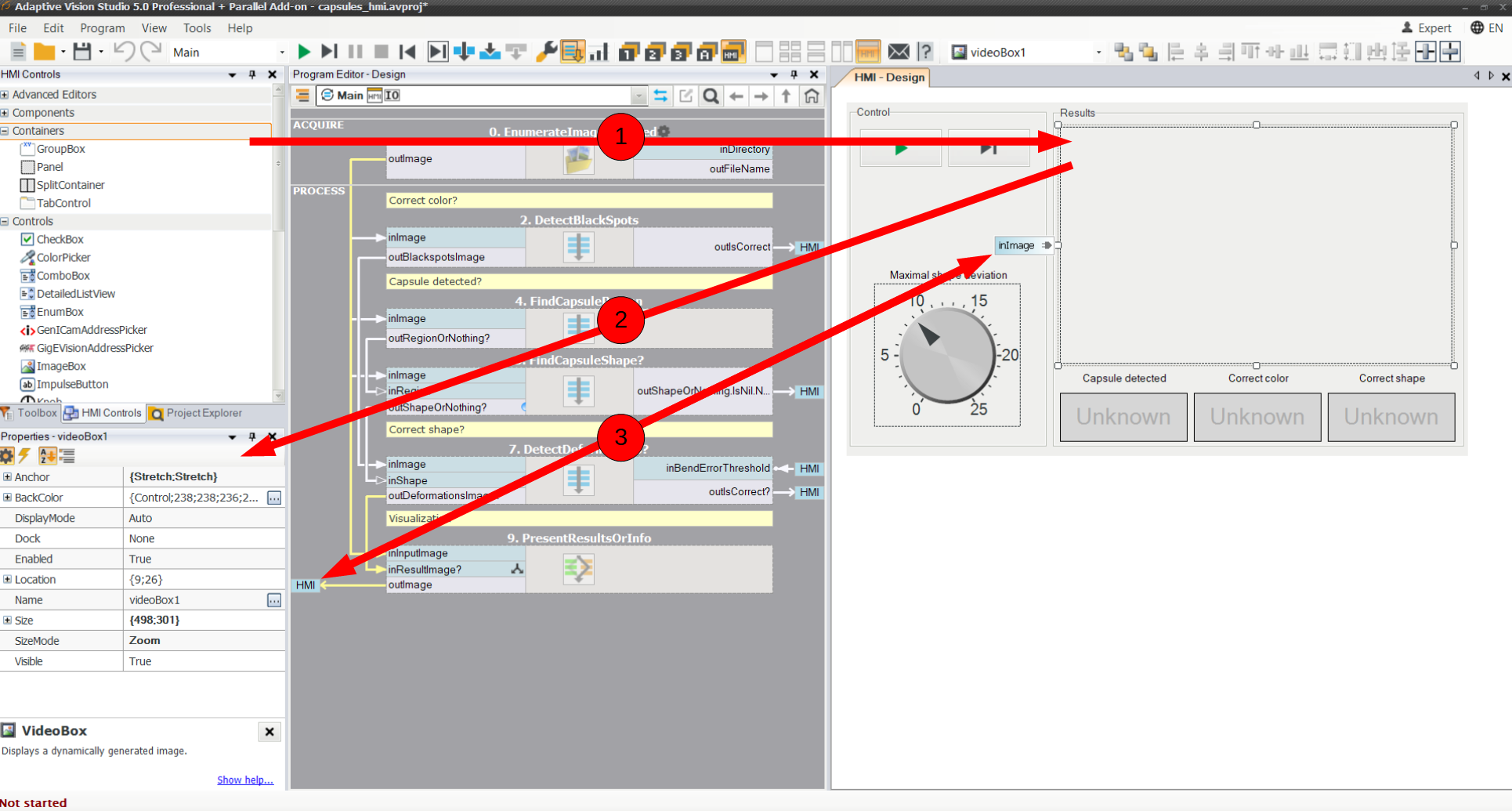
The three steps of HMI design.
The stages of HMI design are explained below:
-
The controls can be dragged onto the HMI Canvas, just as the filters are dragged to the Program Editor panel. To align widgets relative to each other, snaplines can be used. The layout can be organized with the help of containers.
Snaplines assist in setting layout of the controls.
You can also use Anchor and Dock properties to let the control adapt its dimensions to the size of the application window:
- Anchor set to Right or Bottom keeps the control in a fixed distance from the right or bottom edge of its parent window.
- Anchor set to Stretch makes the control resize with the parent window, keeping fixed distances from both edges.
- Dock property binds the control to one of the edges of its parent window, or to the entire free space, in such a way, that multiple controls with this property set automatically share the available window space. Please note, that in this case the order of putting the controls on the canvas does matter.
-
Properties of controls include graphical features, i.e. location, size, colors, fonts, borders and backgrounds. There are also properties affecting the control's behavior, like enabling or disabling, the initial contents (text), visibility, automatic size adjustment etc. Finally, specific controls have their own logical properties, usually the value and other configuration properties (minimal and maximal values, steps, defaults).
Note: Make sure that Context Help is visible to quickly access a short description of each property:
-
Connecting HMI controls is very similar to connecting filter inputs and outputs. First, the control which we want to connect has to be selected. Labels of inputs and outputs of the control will appear next to it. Then one should drag an output of a control onto a compatible filter input, or an output of a filters onto a compatible input of a control.
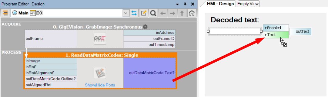
Connecting a filter with a control.
Adaptive Vision Studio will assist this process, by disallowing connections between incompatible ports. After the connection is made, the input or output label will include a little plug icon, and the connected filter will have an "HMI" label next to its input or output.
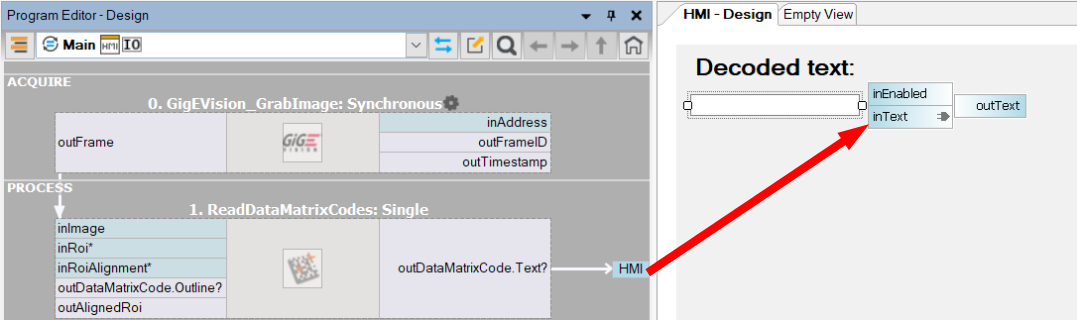
Connection between a filter and a control was established.
Note: If the HMI Editor is undocked, please make sure that it does not overlap with Program Editor before creating a connection.
If we need to remove a connection between a filter and an HMI control, we can right-click the label of either the input or the output. The context menu will include an option to remove the connection.
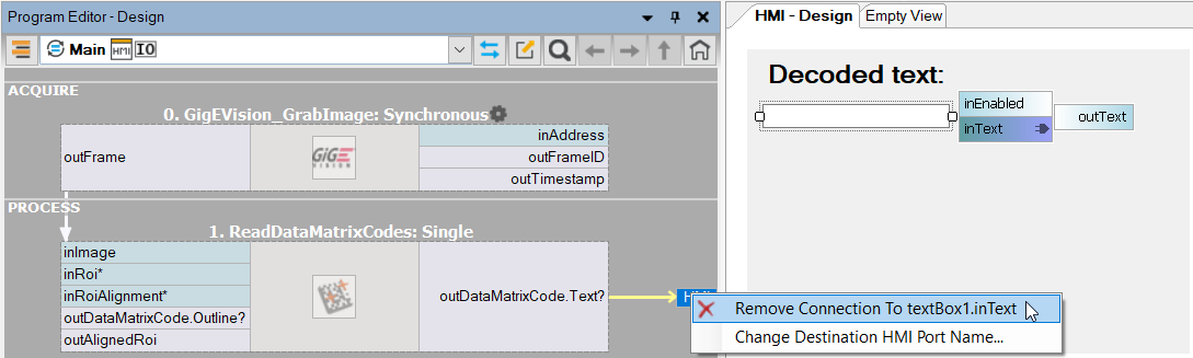
Disconnecting a control from a filter in Program Editor.
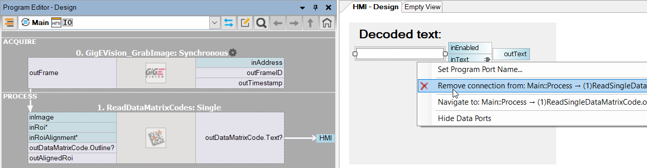
Disconnecting a filter from a control in HMI Designer.
HMI Interactions with the Program
IMPORTANT: During program execution HMI controls exchange data with filters in precisely defined moments:
- Data is sent from HMI controls to filters at the beginning of each iteration of a macrofilter that has any connections with the controls.
- Data is sent in the opposite direction – from filters to HMI – at the end of each iteration.
This has some important implications:
- You CAN connect an output of an HMI control to several filters in a macrofilter and they will be guaranteed to receive exactly the same value in the same iteration.
- You can NOT send a value to a control and expect that this value will be immediately available when a next filter tries to read it. It will be available only in the next iteration. The next filter in the current iteration will still read the old value.
-
If you have a task nested in another task the order of data transfers may become surprising – e.g. results of the outer tasks are not displayed until the inner task terminates.
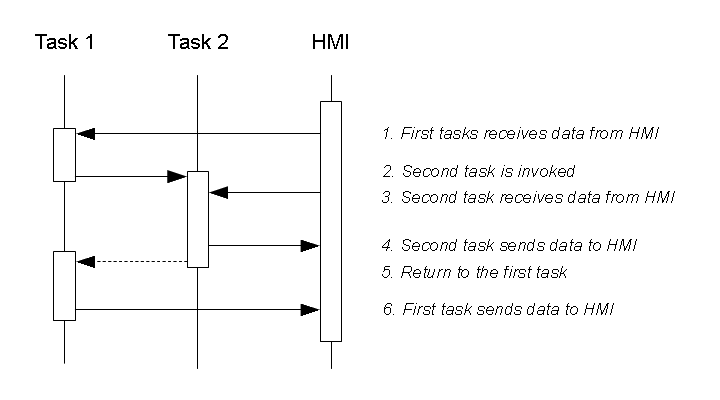
Sample communication structure when one task is nested in another. Please note, that Task 2 will often operate in a loop making it very long before Task 1 sends data to the HMI.
Recommendations
To handle communication between filters and controls efficiently, we recommend the following rules:
- Avoid nested loops (tasks) with HMI communication. Instead:
- Either create a single Finite State Machine per application. For example, instead of waiting in a nested loop for the user to click a button, create an application state named "Waiting" with a transition to another state on the button click event.
- Or create a "master" task without any HMI communication, with two or more nested tasks that do have HMI communication and represent different phases of the application. Fox example, the master may be the "Main" macrofilter with a loop and two sub-tasks named "WaitForStart" and "RunInspection".
- If one program iteration takes long time, but communication has to be performed at very specific moments, use a nested macrofilter just for sending or receiving data to or from HMI. This nested macrofilter will enforce communication moments. Use CopyObject filters when no direct connection from the Macrofilter Inputs block to HMI controls are possible. See also: Sending Values to HMI from Multiple Places below.
- Avoid complex dependencies between HMI controls (i.e. setting properties of one control using values set by the user in another control). Doing so would require sending values around through filters or registers in the program. An exception from this rule is the "Auto Value" feature of the Label control, which allows to link a label content with values set in such controls as TrackBar or Knob.
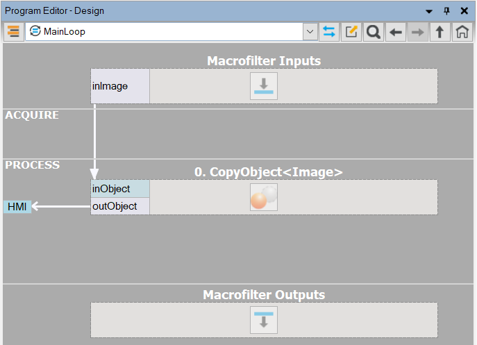
- Keep the program structure simple and clear. For most applications there should be a single loop consisting of three parts: (1) image acquisition, (2) image processing, (3) preparing data for the hmi. We recommend that all connections with HMI are created on the top level of the main loop as can be seen on the picture below:
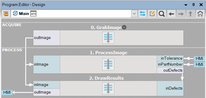
A typical simple structure of a program with HMI connections.
Sending NIL Values to HMI
It is also possible to send conditional values from filters to HMI controls. When a Nil value is sent then the control's property remains unchanged. This may be useful when both the program and the user modify the same property (e.g. the position of a track-bar). Is such cases, data sent to the control from the program should be conditional, so that it does not override the value set by the user.
Sending Values to HMI from Multiple Places
Each input of an HMI control can only have one source of data in the program. However, sometimes it is required that values to that control are sent from several different places. For example, a VideoBox display can be connected with the output of a GigEVision_GrabImage filter, but we might also want to send an empty image to that control when an error occurs. This can be achieved by creating a macrofilter with one or several inputs and with the same number of CopyObject filters connected with the HMI (direct connections from macrofilter inputs to the HMI are not permitted). That macrofilter can then be then used in many times in the program, effectively allowing for explicit communication with the HMI from multiple places.
Sample macrofilter for explicit communication with HMI from multiple places of a program.
Preparing Data for Display in HMI
There is a significant difference between how inspection results are visualized in the standard data preview windows (development environment) and in HMI (runtime environment). On data preview windows multiple data items are just dragged & dropped, and properties such as color or line thickness are selected automatically. This is highly suitable for quickly analyzing data in application development process. In HMI (runtime environment), however, we want to have full control over visualization style of each single element. Thus, before sending data to HMI controls such as VideoBox (for images) or Label (for text), the user has to prepare visualization by using appropriate filters, such as:
- Image Drawing – for preparing images overlaid with geometrical primitives, text labels etc.
- CropImage, ResizeImage, MirrorImage etc. – for transforming an image in an arbitrary way before display.
Note: ZoomingVideoBox control has a built-it support for panning and zooming the displayed images, so no additional filters are required.
- FormatRealToString, FormatIntegerToString, FormatPoint2DToString etc. – for formatting numerical values into strings with properties such as the number of decimal digits or the fractional digits separator.
- ConcatenateStrings, StringToUpperCase, Substring etc. – for displaying textual values in a specific way.
Example 1:
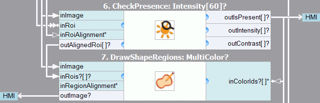
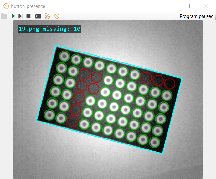
In a button inspection application we detect buttons and check if each button is present or not. We want to display green or red circles over the buttons, indicating the inspection results.
The solution is to use DrawShapeRegions_MultiColor filters with its inColorIds input connected from the outIsPresent output of the CheckPresence_Intensity filter:
|
|
If more overlays are required on a single image, then we use multiple Image Drawing filters connected sequentially.
Note: If many drawing filters are connected in a sequence, then performance may suffer as Adaptive Vision Studio keeps a copy of an image for each of the filters. A recommended work-around is to encapsulate the drawing routine in a very simple user filter – because on the C++ level (with AVL Lite library) it is possible to do drawing "in place", i.e. without creating a new copy of the image. Please refer to the "User Filter Drawing Results" example in Adaptive Vision Studio. Make sure you build it in the "Release" configuration and for the appropriate platform (Win32 / x64).
Example 2a:
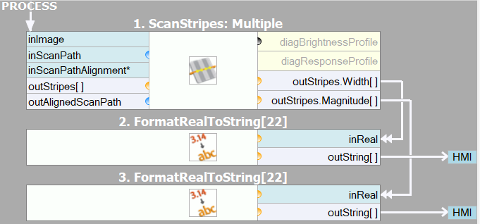
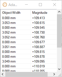
The ScanMultipleStripes filter has an output named outStripes.Width and outStripes.Magnitude, which are of RealArray type. We want to display these numbers in the HMI with a DetailedListView control, which has several inputs of StringArray type.
The solution is to convert each Real number into a String using FormatRealToString filter. On the pictures below demonstrated is the visualization of two columns of numbers with different parameters used in the formatting filters:
|
|
Example 2b:
If a similar array of numbers is to be displayed in a Label control, which has a single String on the input (not an array), then some more preprocessing is still required – in the FormatRealToString filter we should add a new-line character to the inSuffix input and then use ConcatenateStrings_OfArray to join all individual strings into a single one.
See Also
| Previous: HMI | Next: Standard HMI Controls |