
You are here: Start » Programming Tips » Programming Finite State Machines
Programming Finite State Machines
Introduction
Industrial applications often require the algorithm to work in several different modes. Two most typical examples are:
- An application that has several user interface modes, e.g. the inspection mode and the model definition mode.
- An application that guides a robot arm with modes like "searching for an object", "picking an object" etc.
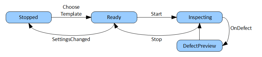
Such applications are best described and programmed as Finite State Machines (FSM). Below is an example diagram depicting one in a graphical way:
Instructions
In Adaptive Vision Studio, Finite State Machines can be created with variant macrofilters and registers. The general program schema consists of a main loop macrofilter (a task, usually the "Main" macrofilter) and a variant macrofilter within it with variants corresponding to the states of the Finite State Machine. Individual programs may vary in details, but in most cases the following instructions provide a good starting point:
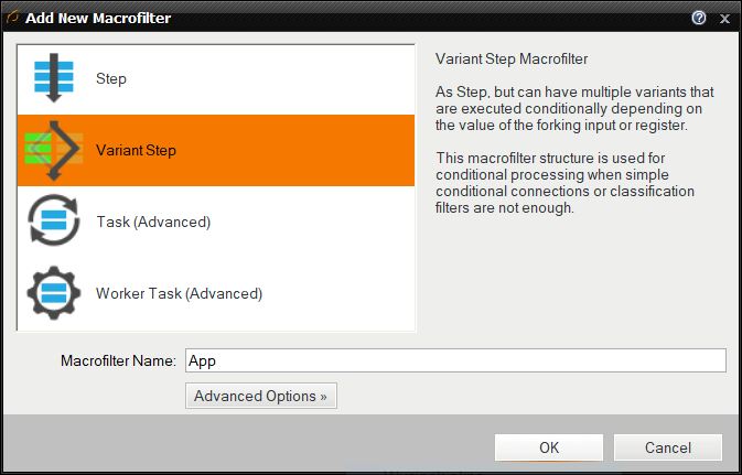
- Create a Variant Step macrofilter (e.g. "App") for the State Machine with variants corresponding to individual states.
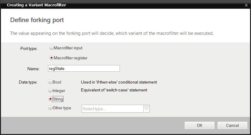
- Use a forking register (e.g. "regState") of the String type, so that you can assign clear names to each state.
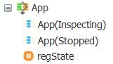
- At first, you will have only one default variant. Remove it and add one variant with a meaningful label for each state.
- Do not forget to set an appropriate initial value for the forking register (the initial state).
- Add macrofilter inputs – usually for the input image and major parameters.
- Add macrofilter outputs that will contain information about the results. In each state these outputs can be computed in a different way.
- Create an instance of this variant macrofilter in some task with a loop, e.g. in the "Main" macrofilter.
- In each state compute the value of the next state and connect the result to the next port of the forking register. Typically, an HMI button's outputs are used here as inputs to formula blocks.
- Optional: Create a formula in the main loop task for enabling or disabling individual controls, depending on the current state (also requires exposing the current state value as the variant step's output).
Example
For a complete example, please refer to the "HMI Start-Stop" example program. It is based on two states: "Inspecting" and "Stopped". In the first state the input images are processed, in the second they are not. Two buttons, Start and Stop, allow the user to control the current state.
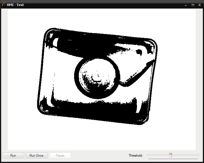
An example application with a simple Finite State Machine
Note: There is also a standard control, ProgramControlBox, which provides "Start", "Iterate" and "Pause" buttons. It is very easy to use, but it is not customizable. Finite State Machines allow for creating any custom set of states and transitions.
Blocking Filters
Please note that while using the Finite State Machine approach to create more complex program logic, you should avoid the use of image acquisition filters configured for the triggered mode (e.g. GigEVision_GrabImage). These filters are blocking, which means that the program execution will halt waiting for the trigger and no other computations are performed during this time. Events, such as button clicks, will not get processed until the next image is acquired.
If your application is using a camera or multiple cameras in the triggered mode, then it is advisable to use filters with timeout – GigEVision_GrabImage_WithTimeout or GenICam_GrabImage_WithTimeout. These filters return Nil after the time is out and no image has been acquired. It is thus possible to use them in a loop, in which events can be processed and the inspection part is executed conditionally – only when there is a new input image.
See also: Handling Events in Low Frame-Rate Applications.
| Previous: Dealing with Domain Errors | Next: Recording Images |