
You are here: Start » Function Reference » Shape Fitting » AvsFilter_FitPathToEdges

AvsFilter_FitPathToEdges
This is Filter Equivalent. This function may be present in generated code, but should not be used in hand-written code. CreatePathFittingMap and FitPathToEdges should be used instead.
Performs a series of 1D edge detections and creates a path from the detected points.
| Header: | AVL.h |
|---|
Syntax
void avs::AvsFilter_FitPathToEdges
(
	FitPathToEdgesState& ioState,
	const avl::Image& inImage,
	const avl::PathFittingField& inFittingField,
	atl::Optional<const avl::CoordinateSystem2D&> inFittingFieldAlignment,
	atl::Optional<float> inScanStep,
	int inScanWidth,
	const avl::InterpolationMethod::Type inImageInterpolation,
	const avl::EdgeScanParams& inEdgeScanParams,
	avl::Selection::Type inEdgeSelection,
	atl::Optional<const avl::LocalBlindness&> inLocalBlindness,
	atl::Optional<int> inMaxInterpolationLength,
	atl::Optional<float> inMaxDeviationDelta,
	float inMaxIncompleteness,
	atl::Conditional<avl::Path>& outPath,
	atl::Optional<atl::Array<atl::Conditional<avl::Edge1D> >&> outEdges = atl::NIL,
	atl::Optional<atl::Conditional<avl::Profile>&> outDeviationProfile = atl::NIL,
	atl::Optional<avl::PathFittingField&> outAlignedFittingField = atl::NIL,
	atl::Array<avl::Segment2D>& diagScanSegments,
	atl::Array<avl::Rectangle2D>& diagSamplingAreas,
	atl::Array<avl::Profile>& diagBrightnessProfiles,
	atl::Array<avl::Profile>& diagResponseProfiles
)
Parameters
| Name | Type | Range | Default | Description | |
|---|---|---|---|---|---|
| ioState | FitPathToEdgesState& | Object used to maintain state of the function. | |||
 |
inImage | const Image& | Image to fit the path to | ||
|
inFittingField | const PathFittingField& | Path fitting field | ||
|
inFittingFieldAlignment | Optional<const CoordinateSystem2D&> | NIL | Adjusts the fitting field to the position of the inspected object | |
|
inScanStep | Optional<float> | 0.0 -  |
5.0f | Optional implicit conversion of the input path to an equidistant one |
|
inScanWidth | int | 1 - |
5 | The width of each scan field (in pixels) |
|
inImageInterpolation | const InterpolationMethod::Type | Bilinear | Interpolation method used for extraction of image pixel values | |
|
inEdgeScanParams | const EdgeScanParams& | EdgeScanParams ( ProfileInterpolation: Quadratic4 SmoothingStdDev: 0.6f MinMagnitude: 5.0f EdgeTransition: BrightToDark ) | Parameters controlling the edge extraction process | |
|
inEdgeSelection | Selection::Type | Selection mode of edges | ||
|
inLocalBlindness | Optional<const LocalBlindness&> | NIL | Defines conditions in which weaker edges can be detected in the vicinity of stronger edges | |
|
inMaxInterpolationLength | Optional<int> | 0 - |
1 | Maximal number of consecutive points not found |
|
inMaxDeviationDelta | Optional<float> | 0.0 - |
NIL | Maximal difference between deviations of consecutive path points |
|
inMaxIncompleteness | float | 0.0 - 0.999 | 0.1f | Maximal fraction of edge points not found |
 |
outPath | Conditional<Path>& | Fitted path or nothing if the fitting failed | ||
|
outEdges | Optional<Array<Conditional<Edge1D> >&> | NIL | Found edges | |
|
outDeviationProfile | Optional<Conditional<Profile>&> | NIL | Profile of distances between the actual path points and the corresponding reference path points | |
|
outAlignedFittingField | Optional<PathFittingField&> | NIL | Fitting field used; in the image coordinate system | |
 |
diagScanSegments | Array<Segment2D>& | Segments along which the scans were run | ||
|
diagSamplingAreas | Array<Rectangle2D>& | Areas from which the input image is sampled | ||
|
diagBrightnessProfiles | Array<Profile>& | Extracted image profiles | ||
|
diagResponseProfiles | Array<Profile>& | Profiles of the edge (derivative) operator response |
Description
The operation tries to fit a given path to edges present in the inImage image. Internally, it performs a series of scans with the ScanSingleEdge filter along a number of specific scan segments which length is always equal to the inFittingField width and cannot be less than 4. The found points are then used to determine the actual position of the path in the image. Only inMaxIncompleteness fraction of these scans may fail. If the fitting according to the given parameters is not possible, outPath is set to Nil.
There are also another parameters that control the path fitting process. The inMaxDeviationDelta parameter defines the maximal allowed difference between deviations of consecutive points from the input path points. If some of the scans fail or if some of found points are classified to be wrong according to another control parameters, output path points corresponding to them are interpolated depending on points in their nearest vicinity. No more than inMaxInterpolationLength consecutive points can be interpolated. The exception to this behavior are points which were not found on both ends of the input path. Those are not part of the result at all.
Hints
- Connect an input image to the inImage input.
- Define inEdgeScanParams.EdgeTransition to detect a particular edge type, and only that type.
- If no or too few edge points are found, try decreasing inEdgeScanParams.MinMagnitude.
- If some of the scans may fail, set the inMaxIncompleteness input accordingly.
- Use the outEdges outputs to visualize the scanning results.
Examples
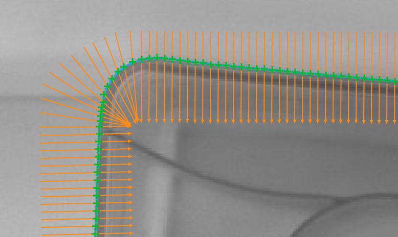
Fitting a path to the edges of a plastic capsule
(inEdgeSelection = First, inEdgeScanParams.EdgeTransition = BrightToDark).
Remarks
For more information about local coordinate systems please refer to the following article.
This filter is a part of the Shape Fitting toolset. To read more about this technique, one can refer to the Shape Fitting chapter of our Machine Vision Guide
Hardware Acceleration
This operation supports automatic parallelization for multicore and multiprocessor systems.
See Also
- AvsFilter_FitPathToRidges – Performs a series of 1D ridge detections and creates a path from the detected points.
- AvsFilter_FitPathToStripe – Performs a series of 1D stripe detections and creates a path from the detected points.
- CreatePathFittingMap – Precomputes a data object that is required for fast path fitting on images.