
You are here: Start » Filter Reference » Computer Vision » Camera Calibration » CalibrateCamera_LineScan (CalibrateCamera LineScan)
 Advanced
| Module: | Calibration |
|---|
Finds the line scan camera intrinsic parameters from calibration grid.
Applications
| Name | Type | Range | Description | |
|---|---|---|---|---|
 |
inImageGrid | AnnotatedPoint2DArray | Annotated calibration grid | |
|
inGridSpacing | Real | 0.000001 -  |
Real-world distance between adjacent grid points. |
|
inImageWidth | Integer | 1 - |
Image width, used for initial estimation of principal point. |
|
inDistortionType | LensDistortionModelType | Lens distortion model | |
|
inImagePointsStandardDeviation | Real | 0.0 - |
Assumed uncertainty of inImagePoints. Used for robust optimization. |
|
inFocalLength | Real* | Specify a fixed focal length, in pixels. In order to calculate the inFocalLength from camera parameters one needs to divide the lens focal length [mm] by sensor pitch [mm/pix]. | |
 |
outCameraModel | LineScanCameraModel | ||
|
outApproxScaleRatio | Real | Approximate scale ratio between Y and X. Useful for camera/encoder trigger rate configuration. When greater than 1, the image is stretched in Y dimension, when less than 1 it is compressed. | |
|
outRmsError | Real | Final reprojection RMS error, in pixels. | |
|
outMaxReprojectionError | Real | Maximum reprojection error among all points. | |
|
outReprojectionErrorSegments | Segment2DArray | Array of segments connecting input image points to grid reprojections. | |
Description
The filter estimates intrinsic parameters of whole line scan camera system, which consist of a camera and a moving conveyor belt. Such approach, in contrast with area scan camera calibration, is necessary as the moving element of line scan camera system is tightly bound within the image acquisition geometry. This allows for handling distortions caused by:
- intrinsic lens distortions
- image shear caused by deviation from right angle between conveyor belt motion and the camera line
- nonuniform image scaling caused by deviation from ideal encoder trigger period
- 1D perspective effects caused by deviation from right angle between camera optical axis and the imaged plane
Calibration uses a planar calibration grid to perform robust minimization of RMS reprojection error - the square root of averaged squared distances between grid points as observed on the image and their associated grid coordinates projected onto image plane using estimated parameters.
The calibration routine cannot estimate focal length by itself, however it can be set to a fixed value via inFocalLength. The inFocalLength is measured in pixels, it can be calculated from the sensor and lens parameters:

where f_pix - focal length measured in pixels, f_lens - focal length of lens measured in millimeters, pp - sensor pixel pitch measured in millimeters per pixel, d - camera binning or/and image downscaling factor
The inFocalLength can also be obtained from angle of view:
where f_pix - focal length measured in pixels, w - image width, alpha - angle of view
Only the divisional and polynomial lens distortion models are supported for line scan cameras. The divisional supports most use cases and has predictable behaviour even when calibration data is sparse. Polynomial model may be more accurate but it needs a larger dataset of high quality calibration points across the whole image.
The filter provides a few methods for judging the feasibility of calculated solution.
- The outRmsError is the final RMS reprojection error. The main contributor to that value is the random noise in inImageGrid points positions. Model mismatch will also result in increased outRmsError.
- The outMaxReprojectionError is the maximum reprojection error, can be used to judge if there are outliers in the calibration data.
- The outReprojectionErrorSegments consists of segments connecting input image points to reprojected world points, and thus it can be readily used for visualization of gross errors. The XY scatter plot of residual vectors (obtained by using SegmentVector on the outReprojectionErrorSegments) is a good insight into the residuals distribution, which in ideal case should follow a 2D gaussian distribution centered around point (0,0).
Hints
- High accuracy camera calibration needs a considerable amount of high quality calibration points, especially when using more complicated models. Calibration image should contain hundreds of calibration points spanning the area of interest. The calibration grids should be as flat and stiff as possible (cardboard is not a proper backing material, thick glass is perfect). Take care of proper conditions when taking the calibration images: minimize motion blur by proper lighting, prevent reflections from the calibration surface (ideally use diffusion lighting).
- When the focal length of the camera is not provided via inFocalLength, the calculated model will lack that value. Despite that, some operations will still work properly, such as distortion removal, or basic image to world plane calibration (CalibrateWorldPlane).
Examples
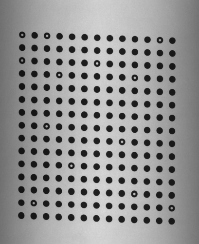 |
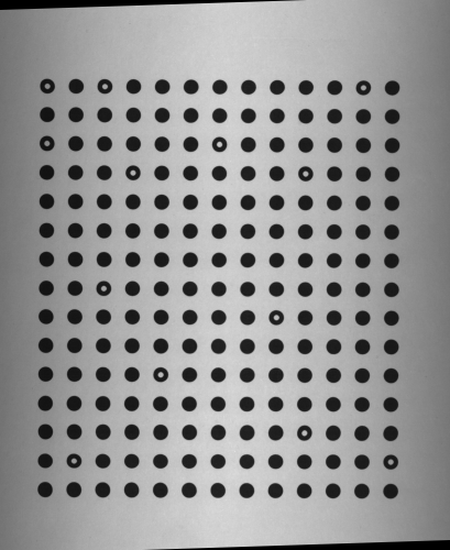 |
Left: calibration grid as captured by the line scan camera. Right: rectified image with shear distortion eliminated. |
|
Remarks
Note, that the calibration routine assumes that the camera line spans the image along its width (i.e. consecutive image rows correspond to consecutive camera acquisitions).
Errors
This filter can throw an exception to report error. Read how to deal with errors in Error Handling.
List of possible exceptions:
| Error type | Description |
|---|---|
| DomainError | Empty input grid |
| DomainError | inGridSpacing needs to be positive |
| DomainError | Thin prism lens distortion is not supported for line scan cameras. |
Complexity Level
This filter is available on Advanced Complexity Level.
Filter Group
This filter is member of CalibrateCamera filter group visible as LineScan.
See Also
- CalibrateCamera_Pinhole – Finds the camera intrinsic parameters from calibration grids. Uses pinhole camera model (perspective camera).
- CalibrateCamera_Telecentric – Finds the telecentric camera intrinsic parameters from calibration grids.