
You are here: Start » Program Examples » Chocolate Cookies Inspection 3D
Chocolate Cookies Inspection 3D
Aim:
The task of this example is to segment cookies, count them and measure their dimensions.
Input:
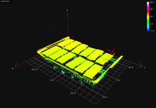
Surfaces of cookies grabbed by a 3D scanner.
Output:
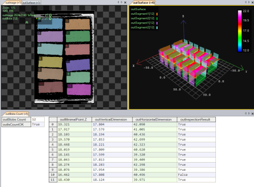
Image of segmented cookies, number of cookies, dimensions and completeness verification.
Hints:
Having acquired point clouds of the Surface data type, try to find a filter which would enable you to convert them into images. Then, you could use Region Analysis technique to perform segmentation. After extracting blobs representing cookies, it is possible to count them and measure their dimensions with the MeasureObjectWidth3D.
Solution (AVS):
-
In Workspace Explorer, open the workspace Examples, and in the Filmstrip window, select the ChocolateCookie dataset. Drag the Surface channel to the ACQUIRE section.
-
Add the CropSurface. Connect the output outSurface to the inSurface. Click on the filter and in Properties window, in the bottom left corner, and set the inZLimits.Min and the inZLimits.Max to 12 and 23 respectively. Set the inPreserveDimensions to True. This way, points corresponding to the background and noise will be removed.
-
Add the CreateImageFromSurface_AnyScales filter to create an image of z-values of the given surface. It allows us to work with 2D tools, even though input data is 3D. Connect the outSurface to the inSurface. Click on the filter and in the Properties window, set the inPixelOffset to 0.
-
Now create a new step macrofilter which you can name e.g. "SegmentAndCountCookies". Connect the outImage and the outSurface to macrofilter inputs. Inside the macrofilter, add the ExtractBlobs_Intensity.
-
Connect the macrofilter input inImage to the inImage. Click on the filter and in the Properties window, set the following values:
- Set inThresholdParams.Polarity to Bright to extract blobs brighter than the background,
- Set inThresholdParams.Threshold to 1 to remove small noise,
- Set inSplittingParams.MinArea to 200000 so that only blobs of the area no lower than that are taken into account,
- Set inSplittingParams.MaxArea to 900000 so that only blobs of the area no greater than that are taken into account.
-
Next, add the ClassifyRegions filter. Connect the outBlobs to the inRegions. Click on the filter and in the Properties window, set the following parameters:
-
Add the RegionUnion_OfArray. Connect the outAccepted to the inArray.
-
Add the CropSurfaceToRegion filter to get a Surface representing only cookies, without points corresponding to the box. Connect the macrofilter inSurface input to the inSurface and the outRegion to the inRegion. Click on the filter and in the Properties window, set the inPreserveDimensions to True.
-
Add an empty Formula and perform the following operations:
- Add a new macrofilter input representing the number of cookies you are expecting to get (e.g. "inExpectedNumberOfCookies" of Integer type) and set its default value to 12. Connect it to the newly-created formula,
- Right-click on the outAccepted output, select Property Outputs and choose the Count property. Connect it to the formula as inNumberOfCookies input,
-
Create a new output in the formula outIsCountOK like this:
outIsCountOK = inExpectedNumberOfCookies == inNumberOfCookies
-
Connect the outIsCountOK output to the macrofilter outputs.
-
Go back to Main and create another step macrofilter (e.g. "FindSurfaceMinimalPoint"). Connect the outSurface from the SegmentAndCountCookies macrofilter to the newly-created macrofilter as an input.
-
Connect the outBlobs from the SegmentAndCountCookies macrofilter as an array connection. It will cause the macrofilter to execute in an array mode (see also: Arrays in Aurora Vision Studio).
-
Inside the macrofilter, add the FillRegionHoles to extend the region so that it contains also the pixels previously lying in its holes. Connect the inRegion input to the inRegion.
-
Add the ErodeRegion to make the region thin enough to find later a minimal point representing the cookie hight. This step is essential since the cookies have rounded edges. Connect the outRegion from the previous filter to the inRegion of the current one. Set the inRadiusX to 30 to remove noise on edges.
-
Add the SurfaceMinimalPoint filter to get the minimal point of the surface within the region obtained in the previous step and connect the inSurface to the inSurface and the outRegion to the inRoi. Drag the outMinimalPoint output to the macrofilter outputs.
-
Go back to Main and create a new step macrofilter to create an individual local coordinate system for each cookie (you may call it e.g. "CreateLocalCoordinateSystem3D"). Connect outSurface and outBlobs from the SegmentAndCountCookies macrofilter to it as new inputs: inSurfaceFormat and inRegion (as an array connection) respectively. The macrofilter will be executed in the array mode as well as the FindSurfaceMinimalPoint macrofilter.
-
Inside the macrofilter, add the RegionBoundingBox_OrNil. Connect the inRegion to the inRegion.
-
Add the CreateCoordinateSystemFromRectangle filter to create an alignment for further analysis. Connect the outBoundingRectangle to the inRectangle.
-
Next, add the ConvertCoordinateSystem2DTo3D to convert the image coordinate system into a 3D coordinate system, because they may not align unless the Surface format is given. Connect the outCoordinateSystem to the inCoordinateSystem. Then, connect the inSurfaceFormat to the inSurfaceFormat.
-
Drag the outCoordinateSystem output to the macrofilter outputs.
-
Go back to Main. Create another step macrofilter (e.g. "MeasureObjectDimensions"). Connect the outSurface from the SegmentAndCountCookies macrofilter and the outCoordinateSystem from the previous macrofilter to inputs of the current one as the inSurface and the inScanFieldAlignment respectively.
-
Inside the macrofilter, add two MeasureObjectWidth3D filters and connect the inSurface and the inScanFieldAlignment to the inSurface and the inScanFieldAlignment in both filters.
-
Now click on the first filter and make the following changes in the Properties window:
- Click on the inScanField and mark the scanning path to compute the height of the cookie,
- Set the inScanCount to 10 to increase the number of scans to be performed,
- Set the inScanWidth to 10 to increase the width of scanning field,
- Set the inStripeScanParams.StripePolarity to Valid - to detect only actual points of the surface representing cookie,
- Set the inMaxProfileGapWidth to 10 which will be the maximal allowed value of profile gap.
-
Click on the other MeasureObjectWidth3D filter and make the following changes in the Properties window:
- Click on the inScanField and mark the scanning path to compute the width of the cookie,
- Set the inScanCount to 10 to increase the number of scans to be performed,
- Set the inScanWidth to 10 to increase the width of scanning field,
- Set the inStripeScanParams.StripePolarity to Valid - to detect only actual points of the surface representing cookie,
- Set the inMaxProfileGapWidth to 400 which will be the maximal allowed value of profile gap,
- Set the inOutlierSuppression to Tukey which will be the best method to ignore incorrectly detected points in this case.
-
Connect both outObjectWidth outputs to the macrofilter outputs as the outVerticalDimension and the outHorizontalDimension respectively.
-
Add an empty Formula with the following inputs:
- inMinVerticalDimension with a default value 7,
- inMinHorizontalValue with a default value 39,
- inMinHeight with a default value 17.
-
Create the following outputs in the formula:
IsVerticalDimensionOK = VerticalDimension > inMinVerticalDimension
IsHorizontalDimensionOK = HorizontalDimension > inMinHorizontalDimension
IsHeightOK = SurfaceMinimalPoint > inMinHeight
InspectionResult = IsVerticalDimensionOK and IsHorizontalDimensionOK and IsHeightOK
Macrofilter Main

Macrofilter CreateLocalCoordinateSystem3D

Macrofilter FindSurfaceMinimalPoint

Macrofilter MeasureObjectDimensions

Macrofilter SegmentAndCountCookies

Used Filters
| Icon | Name | Description |
|---|---|---|
| ClassifyRegions | Use this filter when you have an array of regions and you want to select some of them for further processing. | |
| ConvertCoordinateSystem2DTo3D | Converts a coordinate system connected with the surface image to a coordinate system connected with the surface. | |
| CreateCoordinateSystemFromRectangle | Most often used to define an object alignment from a filter like RegionBoundingRectangle. | |
| CreateImageFromSurface_AnyScales | Allows for performing 2D operations on 3D data. | |
| CropSurface | Removes from the surface points that are not contained in a given rectangular box. | |
| CropSurfaceToRegion | Removes points that are not present in a given region. | |
| ErodeRegion | Making the region thinner or removing small parts. | |
| ExtractBlobs_Intensity | Segments an image into blobs by thresholding using a single value. | |
| FillRegionHoles | Adds pixels to the input region so that it contains no holes. | |
| MeasureObjectWidth3D | Measures the width of an object using stripe detection. | |
| RegionBoundingRectangle_OrNil | Computes the smallest rectangle containing a region; returns NIL if the region is empty. | |
| RegionUnion_OfArray | Computes a region containing all the pixels that any of the input regions contains. | |
| SurfaceMinimalPoint | Finds the surface point with minimal Z coordinate. |
Further Readings
- Blob Analysis - Article presents detailed information about the Blob Analysis technique.
- Formulas - Detailed information about using formulas.
- Geometry 3D - List of filters useful in 3D geometry.
- Surface - Filters performing operations on surfaces in Aurora Vision Studio.