
You are here: Start » Application Notes » Interfacing Hilscher card (EtherNet/IP) to Aurora Vision Studio
Interfacing Hilscher card (EtherNet/IP) to Aurora Vision Studio
Purpose and requirement
This document explains how to configure EtherNet/IP PLC with Aurora Vision Studio using Hilscher EtherNet/IP card.
Required equipment:
- Supported Hilscher EtherNet/IP card
- Aurora Vision Studio 5.1 or later
Hardware connection
All devices must work in a common LAN network, hereinafter called the shared network. In most cases they are connected to each other through a network switch.
The devices shall be connected as follows:
- Master device (e.g. PLC) to the shared network
- Hilscher card to PC
- Hilscher card to the shared network
- PC's network card to shared network
Before proceeding to the further point, make sure that all devices are powered up.
Configuring Hilscher Devices
Be sure to have the newest version of the following drivers:
- List of the EtherNet/IP firmware: download link (for CIFX 50E-RE download V3.x version)
- cifX Driver Setup software (1.5.0.0 version recommended): download link
- SYCON.net to configure Hilscher card and generate configuration files: download link
Make sure you have the recommended driver installed, the newest SYCON.net and firmware prepared.
1) Configuration using cifX Driver Setup Software
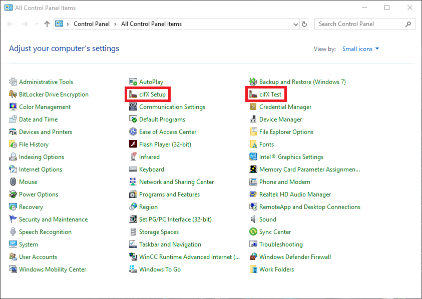
The easiest way to install the firmware to the cifX Driver is using the cifX Driver Setup Software. You can find tools for this software for instance using Control Panel menu as in the picture below.
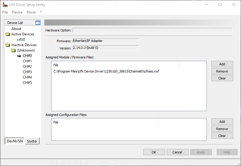
Using cifX Setup application select the channel you would like to configure (usually channel - CH#0) and remove preexisting firmware by clicking "Clear". Then click "Add" to add a new firmware file and navigate to the downloaded Ethernet/IP Adapter firmware (path \COMSOL-EIS V2.15.0.1\Firmware\cifX). Then click "Apply" and finish configuration with "OK".
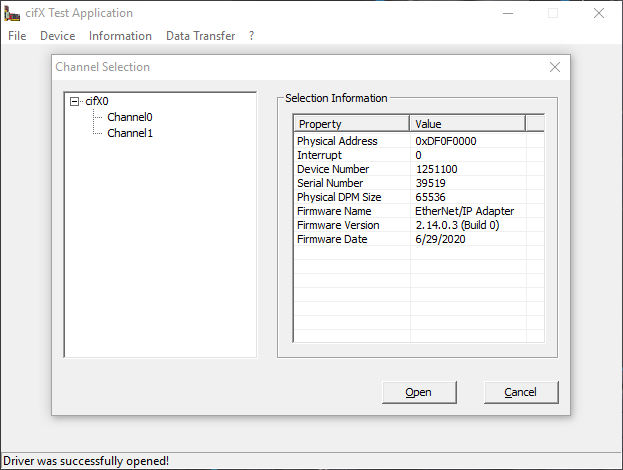
To be sure that firmware is installed properly you can open cifX Test software and then navigate to Device -> Open to achieve the result like below.
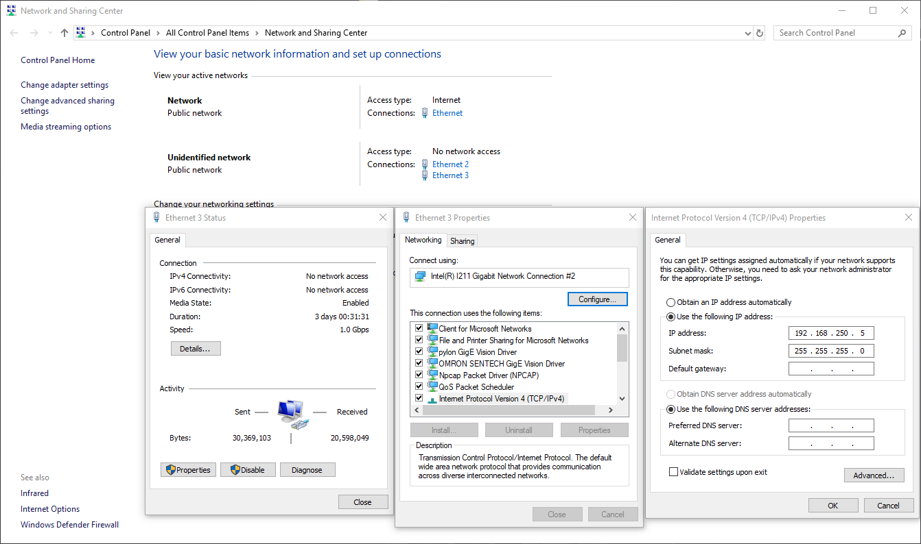
2) Configuration of the network card
It might be necessary to change the IP of the network card from dynamic to static. In this tutorial the following settings are used.
3) Configuration using SYCON.net
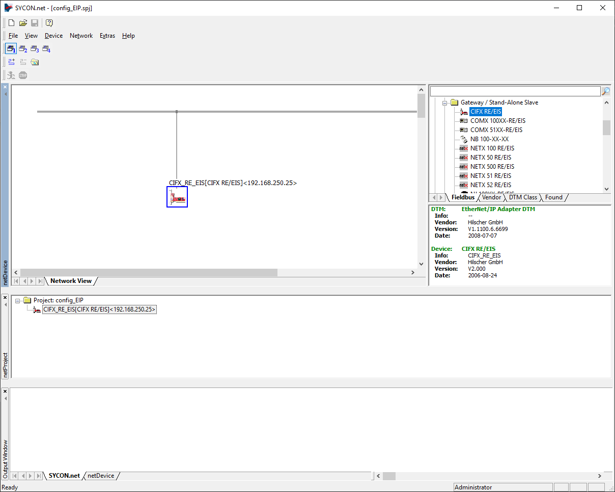
Configuration files are generated in SYCON.net software. Firstly, pick a proper device and drag it to the gray bus on the "Network View". This device you can find navigating to "EtherNet/Ip -> Gateway / Stand - Alone Slave -> CIFX RE/EIS".
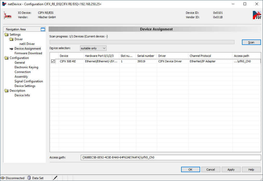
To open the configuration card double click on dropped icon and in the popped-up menu navigate to "Settings/Device Assignment". Then scan for devices by clicking "Scan", mark found one it with a tick like on the image below and then click "Apply".
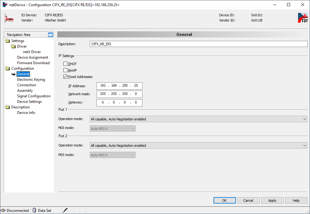
In "Configuration/General" you can change the IP of the device from DHCP to Static like on the below screen.
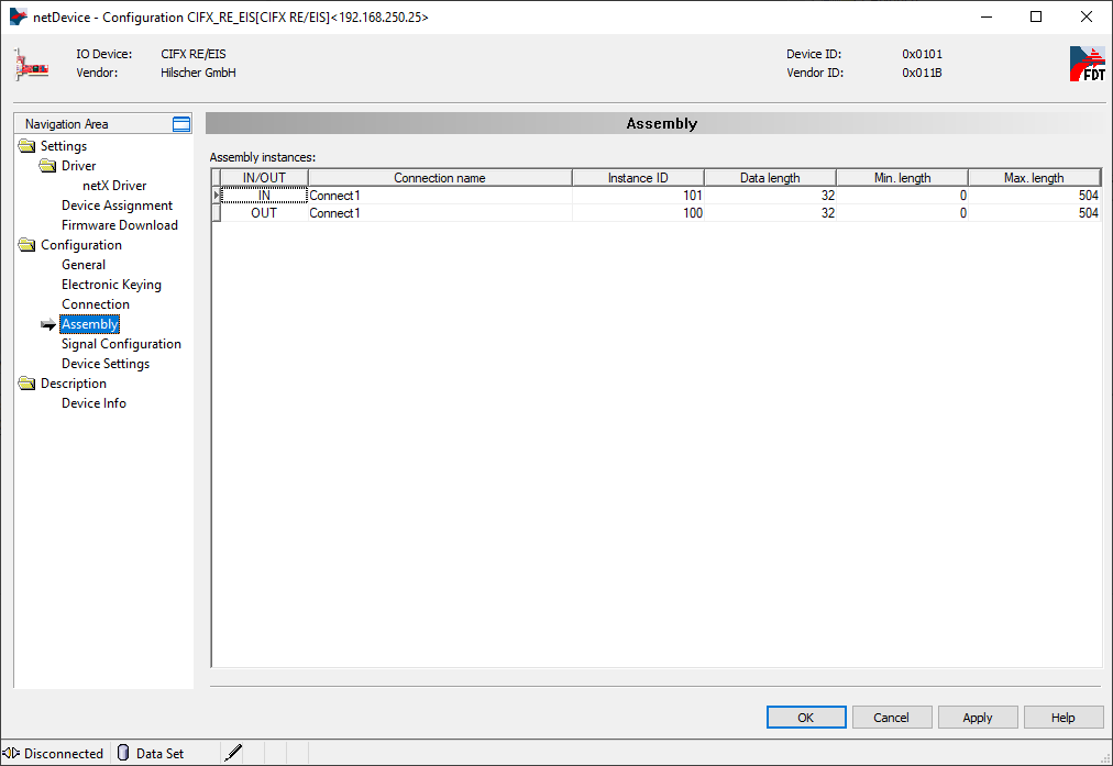
In "Configuration/Assembly" you can change the configuration of memory blocks for IN/OUT operations. By default, the Data length is set to 32 bytes. All subsequent PLC data blocks mentioned in this document are configured for 32 bytes. In case you need memory blocks of a different size, you can change the Data length from 0 up to 504 bytes.
Confirm all changes by clicking "Apply" and then click "OK".
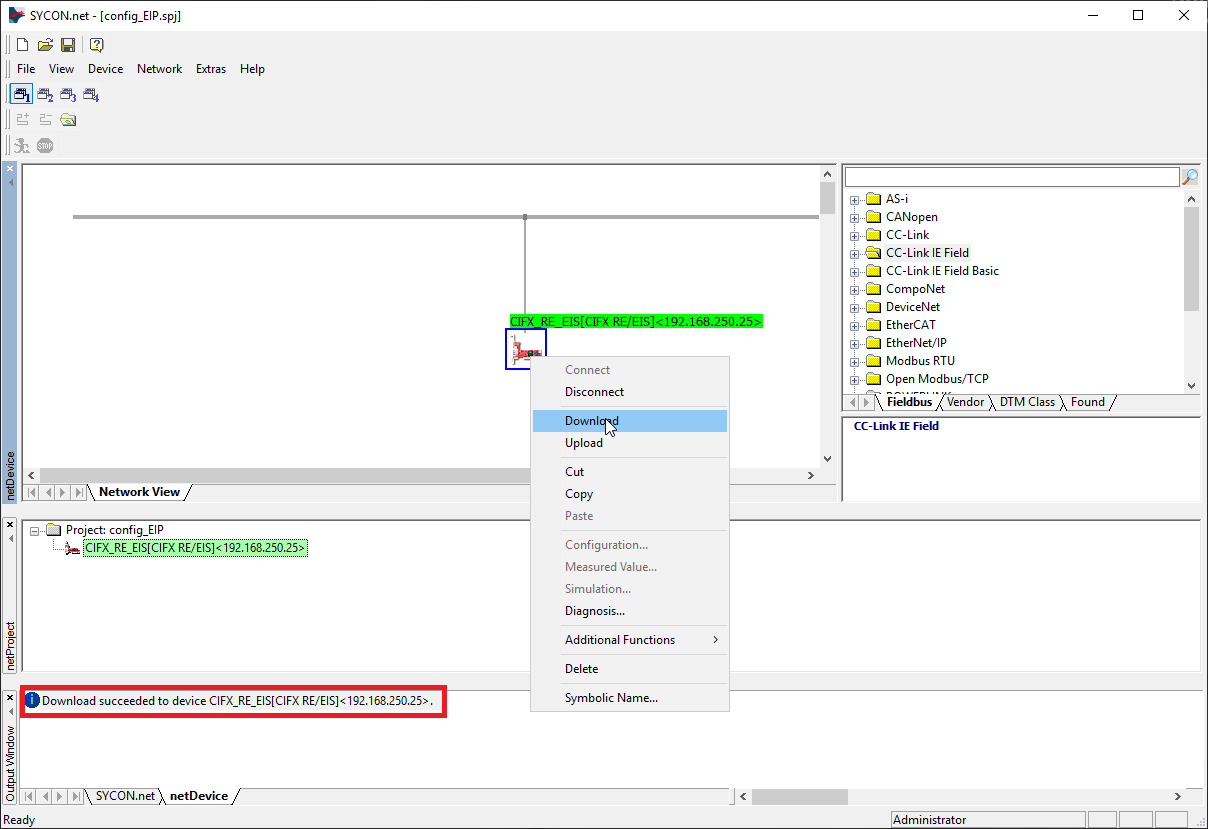
Then you have to download the configuration to the device like on the screen below.
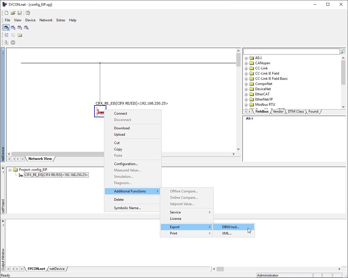
The final step is to generate configuration files for Aurora Vision Studio. You can do this by right-clicking on the device icon, then navigating to "Additional Functions -> Export -> DBM/nxd..", entering your configuration name and clicking "Save". You can now close SYCON.net for this example, remember to save your project before.
4) Example configuration of EtherNet/IP PLC
Below you will find an example configuration process for EtherNet/IP PLC Omron NXJP2-9024DT in Sysmac Studio software.
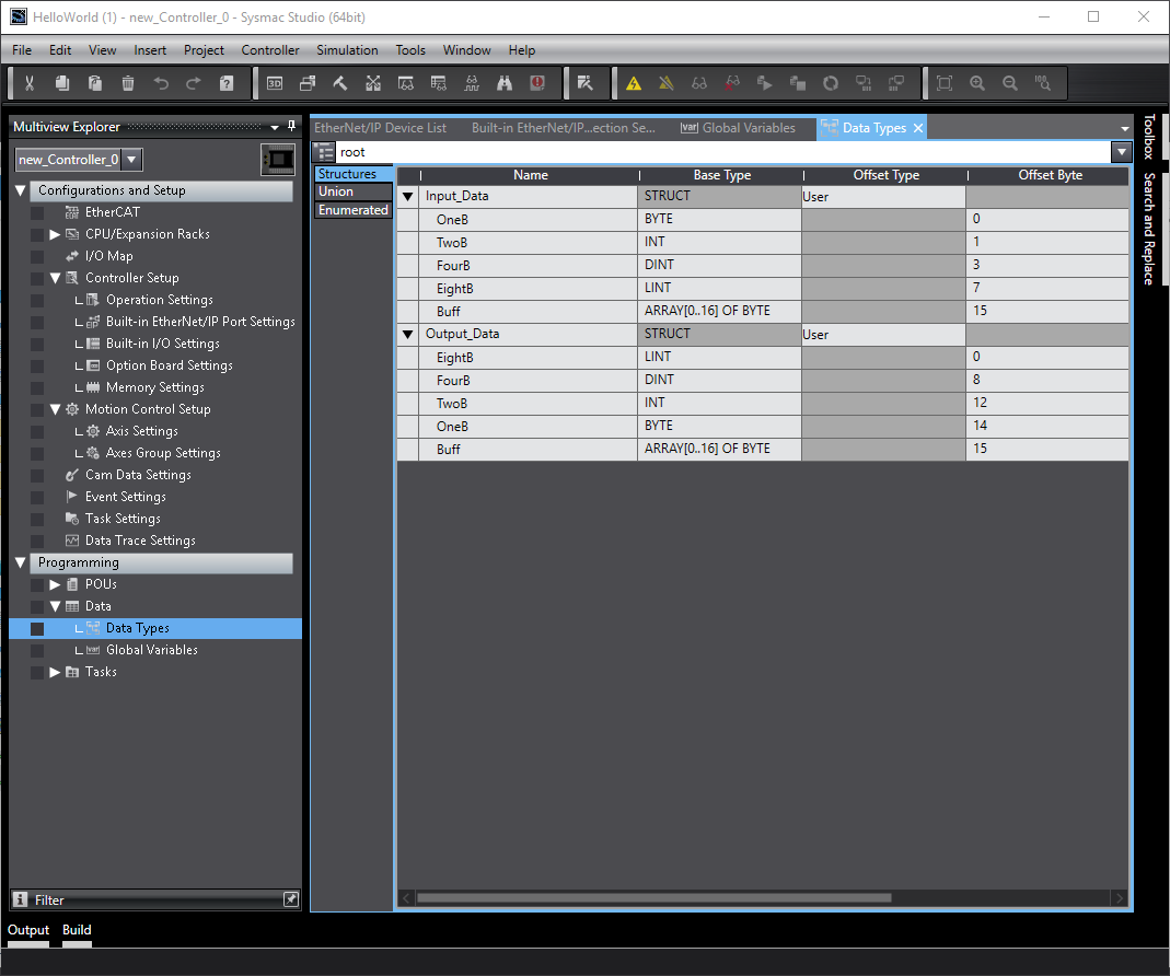
First of all, there were defined two structures Data Types: Input_Data and Output_Data for further tests of Aurora Vision Studio macrofilters. Information about offsets will be further used in Aurora Vision Studio.
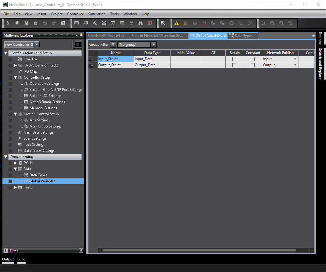
There were created two global variables Input_Struct and Output_Struct using previously created structures to handle communication with Hilscher card.
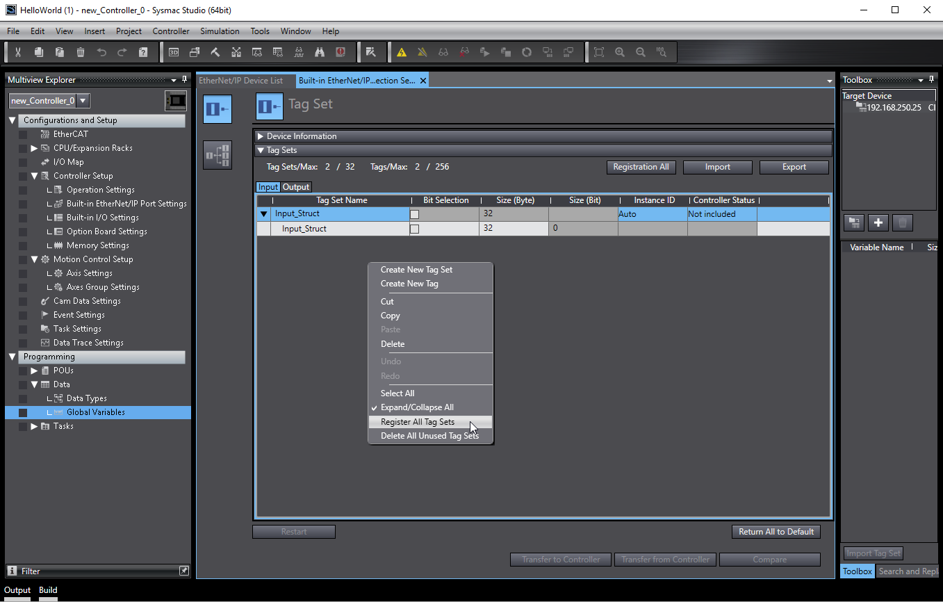
Then navigate to (Tools -> EtherNet/IP Connection Setting) and "Register All Tag Sets".
Add support for Hilscher card using EDS Library configuration (path \COMSOL-EIS V2.15.0.1\EDS). Then add "CIFX RE/EIS" and configure Input and Output like below. It is necessary to match the configuration from SYCON.net.
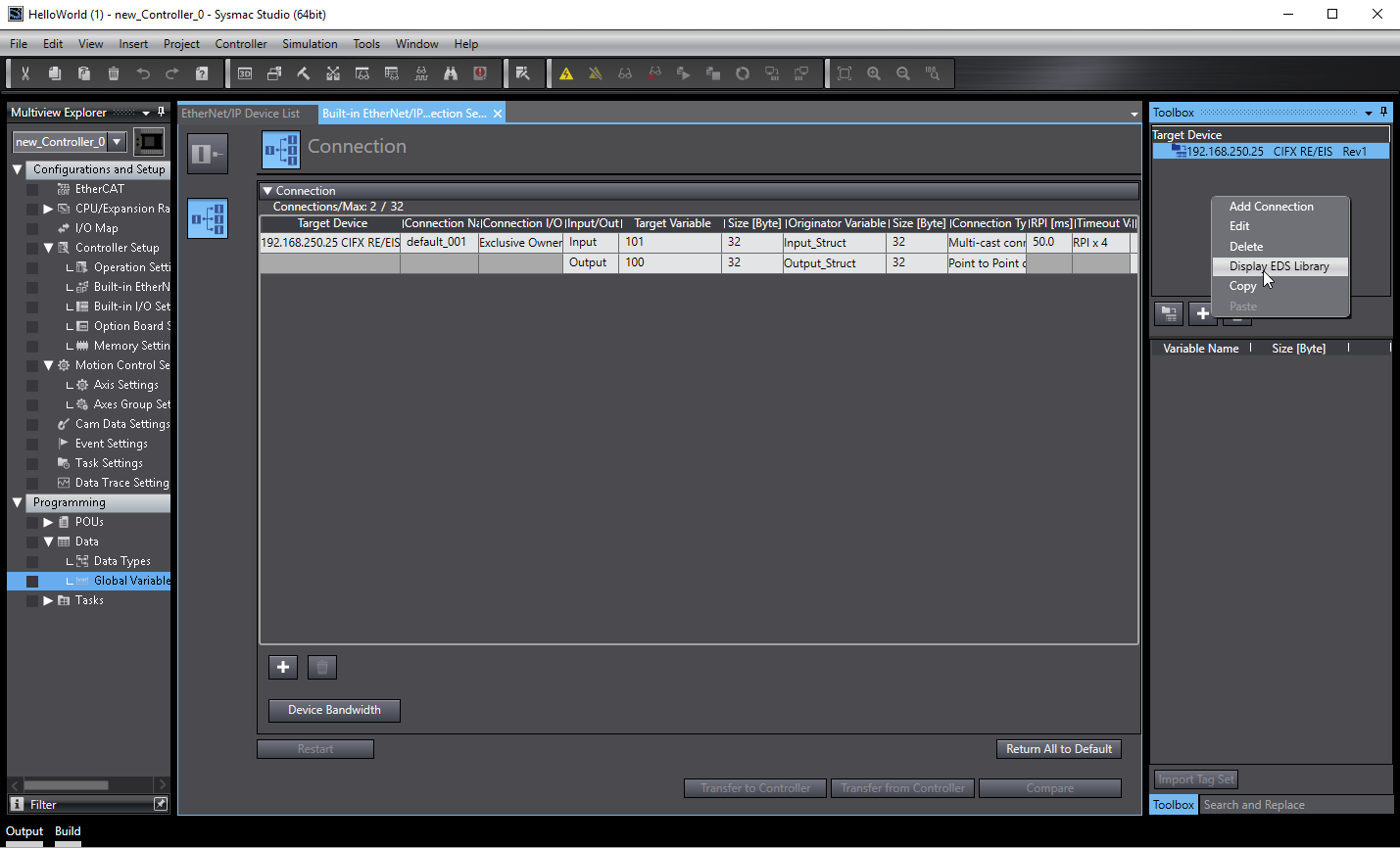 .
.
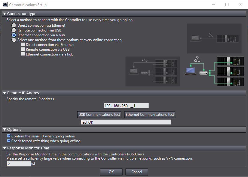
For this moment it is essential to connect with a PLC device, to do this in Sysmac Studio you need to navigate to "Controller -> Communication Setup...". There might be an error in Ethernet Communication Test if your network card is configured as DHCP (Configuration of the network card section in this tutorial). If communication with PLC is established you will receive "Test OK".
If communication with PLC is established you can download the configuration to the device.
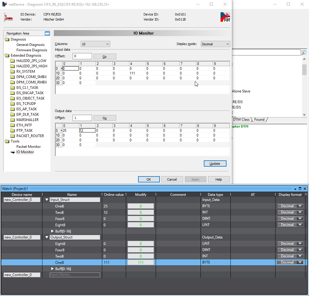
Below you can find a test of input and output memory using a watchtable in Sysmac Studio and IO Monitor in SYCON.net. To turn on IO Monitor you have to right-click on the icon of the card in SYCON.net project and click "Connect". Then double click this icon and navigate to "Tools -> IO Monitor". By clicking "Update" you can send a changed frame to the PLC.
5) Example configuration in Aurora Vision Studio
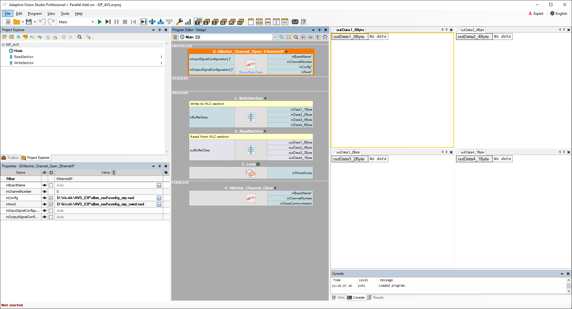
To use EtherNetIP filters in Aurora Vision Studio first you need to attach configuration files from SYCON.net to Hilscher_Channel_Open_EthernetIP filter in INITIALIZE section. The configuration files generated in the previous step are now required in inConfig (xxx.nxd) and inNwid (xxx_nwid.nxd) properties of that filter. Below you can find two Step macrofilters responsible for writing data to PLC and receiving data from it. To have cyclic communication you have to place Loop macrofilter at the end of PROCESS section. In FINALIZE section place Hilscher_Channel_Close macrofilter.
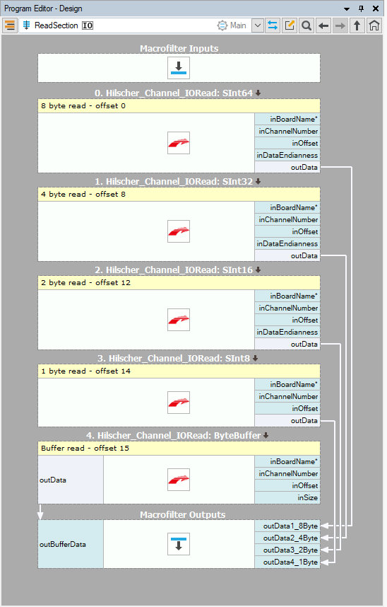
In step macrofilter ReadSection you can find for example Hilscher_Channel_IORead_SInt8 filter which writes 8 bytes of signed data to the predefined memory area. Using different offsets for each macrofilter enables access to different variables created in PLC (Example configuration of Ethernet/IP PLC section of this tutorial).
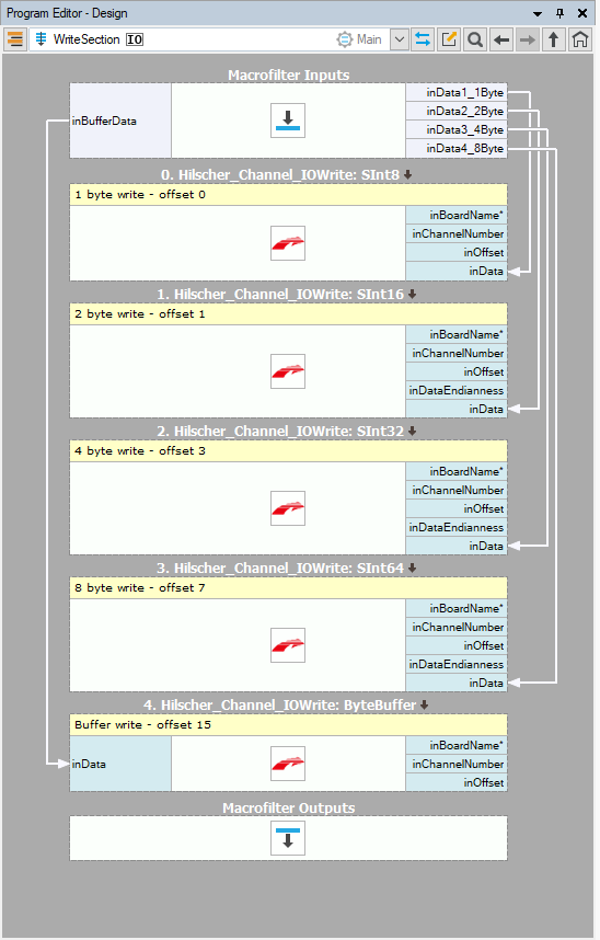
WriteSection step macrofilter has Hilscher_Channel_IOWrite filters (for instance Hilscher_Channel_IOWrite_SInt8) filters with adequate offsets and data types used to match PLC data variables configuration.
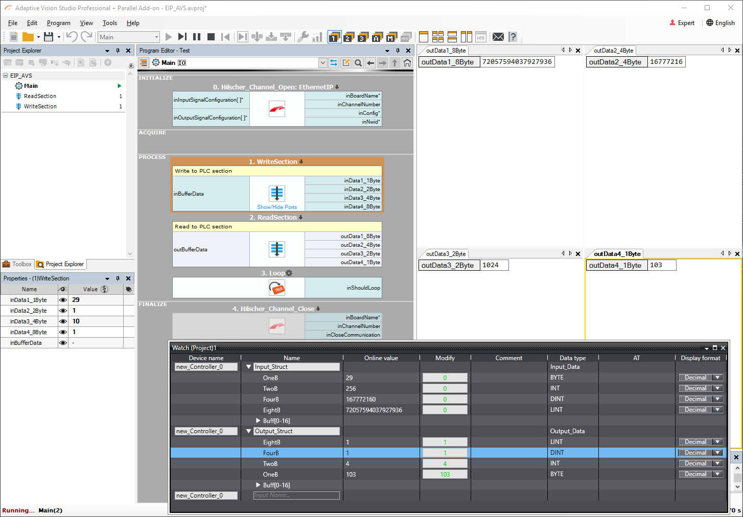
Below is presented reading and writing to PLC with Aurora Vision Studio and Sysmac Studio watchtable. Decimal values of variables are dependent on the data type used.
Troubleshooting
1. Set static IP to Hilscher card. Go to the section Configuration using SYCON.net of this tutorial.
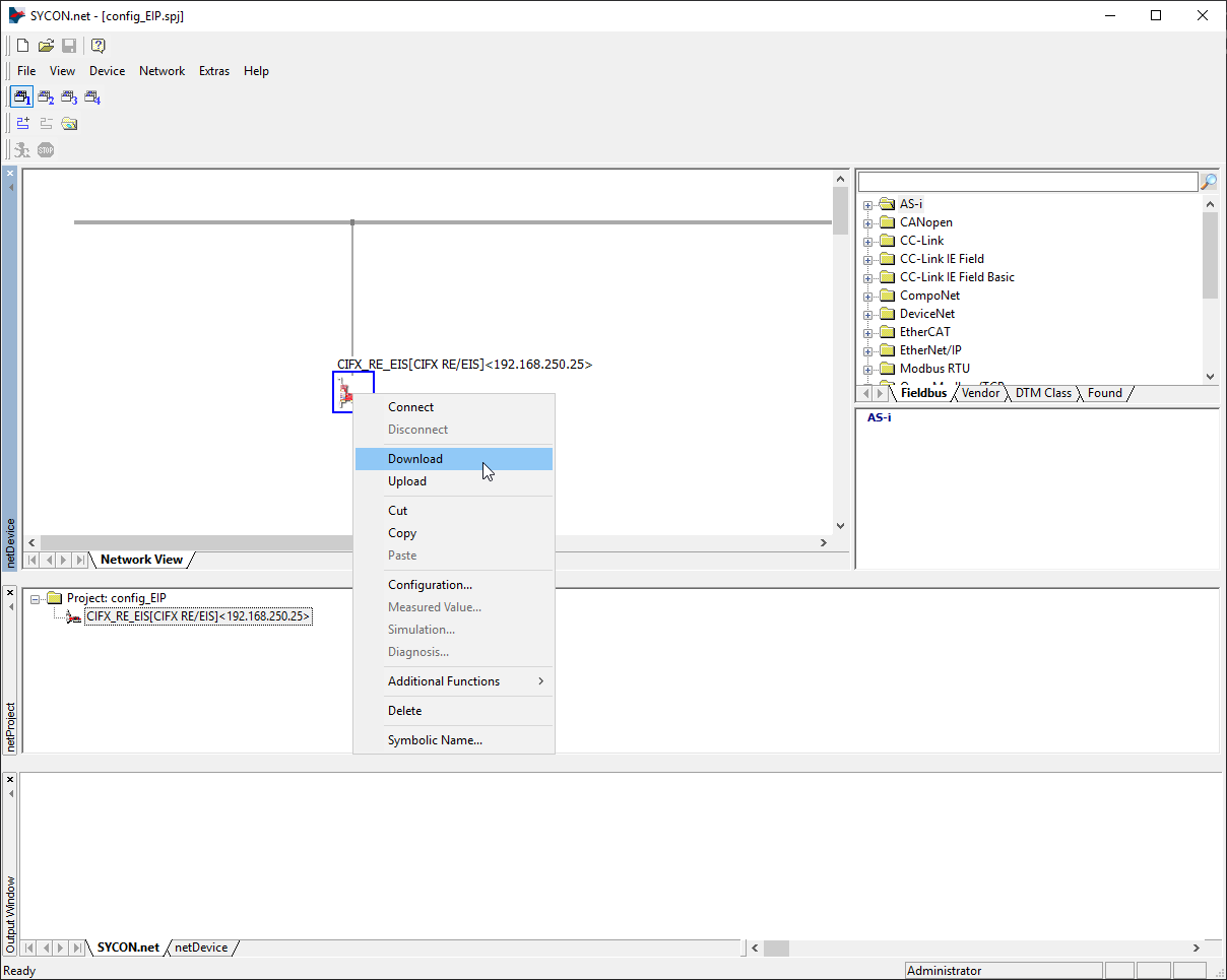
2. Make sure that the current program setting is loaded to the Hilscher card. If not please use SYCON.net application to connect and download settings to the devices as shown in the picture below.
3. Check in your device in Device Assignment. This step was described in Configuration using SYCON.net section of this tutorial.
4. If your master device has a problem with connection with the Hilscher card use the following settings in the SYCON.net application. In order to do this right-click on the card icon and select Configuration...

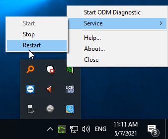
5. After changes it may be necessary to restart ODMV3 service.
6. If none of the above advice has helped, please restart your computer.