
You are here: Start » Filter Reference » Computer Vision » Datacodes » ReadSingleDataMatrixCode
 Basic
Basic| Module: | Datacodes |
|---|
Detects and recognizes one Data Matrix code.
| Name | Type | Description | |
|---|---|---|---|
 |
inImage | Image | Input image |
|
inRoi | Rectangle2D* | Region of interest |
|
inRoiAlignment | CoordinateSystem2D* | Coordinate system for the region of interest |
|
inCodeParams | DataMatrixCodeParams | Specification of codes that can be detected |
|
inDetectionParams | DataMatrixDetectionParams | Parameters of the code detection algorithm |
 |
outDataMatrixCode | DataCode? | A code that has been correctly detected and decoded |
|
outCandidates | PathArray | Diagnostic information about detection results |
|
outAlignedRoi | Rectangle2D | Input ROI after transformation (in the image coordinates) |
Description
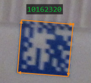
This filter detects and recognizes one data matrix code in an image. If there are more codes the tool may find any of them.
Supported code types: ECC 200 and ECC 000-140.
Groups of parameters
For optimal efficiency the tool may require careful setting of parameters. Most of the parameters are divided into two groups:
- inCodeParams – parameters concerning the code; these can be set precisely according to what codes we expect to read
- inDetectionParams – parameters concerning the algorithm; these may require some experimentation as different approaches may work best in different scenarios
Detection methods
The most important setting is the selection of the code detection algorithm, inDetectionParams.DetectionMethod. The tool offers three options:
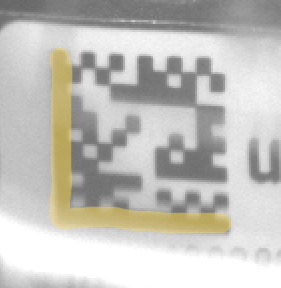
| Quiet Zone | Finder Pattern | Finder Edges | |
|---|---|---|---|
| Where it looks? | 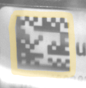 |
 |
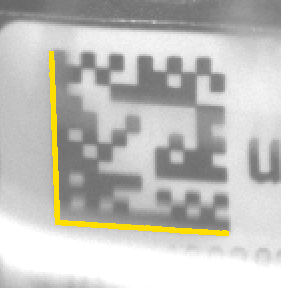 |
| How it works? | Looks for the blank space surrounding the code. In theory it should be empty for a width of at least one module. | Looks for the blob of the L-shaped pattern. In theory it should be continuous and not connected with anything outside of the code. | Looks for the edges of the L-shaped pattern. It uses a robust line segment detector internally. |
| When to use it? | This method is good even for partially broken Finder Pattern, but it will fail if there is any contamination in the Quiet Zone. | This method may deal with some contamination in the Quiet Zone, but it will fail if the Finder Pattern itself is not good. | This method works well even if Quiet Zone is contaminated and Finder Pattern is not perfect, but may be confused by additional lines appearing near the code. |
Pyramid
The tool tries to detect codes at different scale levels. It investigates images at different resolutions, starting with the lowest resolution. If it finds a sufficient number of codes at one level, it may skip looking further, thus achieving shorter execution time. If there are no codes in the input image, it will always scan all the levels, resulting in the highest execution time.
NOTE: If you experience instable execution times, for example switching between 10 ms and 20 ms, it may indicate that for some images the tool finds a code at a higher level, while for some others it has to process the higher resolution too. For that reason, we also recommend testing time performance on the ReadMultipleDataMatrixCodes tool, with inMaxCodeCount=1000 and inAllowMultipleScales=True. This will assure that no early exit happens and the execution time will be the maximum of what we may expect with the given settings.
Finder Tradeoff ("FinderEdges" only)
When using the "FinderEdges" method, you should be aware that there is a tradeoff between the ability of the tool to detect rugged (uneven, noised or dot printed) edges and the ability to detect low contrast edges (or ones neighboring with a very narrow Quite Zone). The default setting is "Balanced". However, if you expect the edges of your code to be relatively straight and clean, but less strong, you may want to change it to "Sensitive". On the other hand, if the edges of the code are highly jagged or the surrounding is noisy, it may be better to choose "Robust". You may also set it to "Auto" and it will test several possibilities at the cost of much higher execution time.
| Use "Sensitive" | Use "Balanced" | Use "Robust" |
|---|---|---|
 |
 |
 |
Distortions
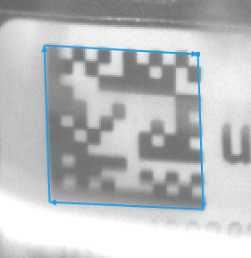
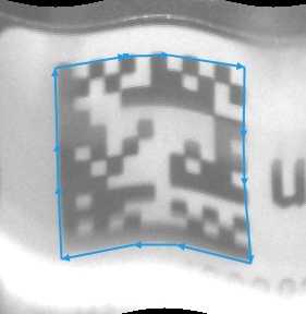
The tool can deal with various types of code deformations. There are three possible settings, as demonstrated below. Please be aware that when we make the algorithm more robust to distortions, at the same time we make it less robust to broken code patterns. For this reason, we should stay with lower settings whenever possible.
| Use "Low" | Use "Medium" | Use "High" |
|---|---|---|
|
 |
 |
 |
 |
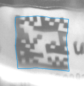 |
| Each side is represented with a single line segment. | Each side is represented with a 3-segment line. | Each side is exactly traced with a polyline. |
Damaged codes and other difficulties
By using appropriate inCodeParams settings you can also find codes that are partially damaged. See the below table for some of the most common cases.
| Use MaxSlant=30 | Use AllowPerspective | Use AllowBrokenFinder and AllowBrokenTiming | Use AllowOversizedModules |
|---|---|---|---|
 |
 |
 |
 |
Hints
- Connect inImage with the output of your image acquisition filter.
- Specify the range of possible codes in an image by setting the inCodeParams input. The more narrow is the specification, the faster the filter works.
- Set inCodeParams.Polarity to specify whether dark-on-bright or bright-on-dark codes are to be read. If code polarity is inconsistent, use "Mixed" (it may be also a very good option of DPM codes).
- Specify the range of possible code sizes with inCodeParams.MinRowCount, inCodeParams.MaxRowCount, inCodeParams.MinColumnCount and inCodeParams.MinColumnCount.
- Specify the range of possible module sizes (in pixels) with inCodeParams.MinModuleSize and inCodeParams.MaxModuleSize.
- Set inCodeParams.ExpectedGapSize according to the following rules:
- Zero – no gaps at all (modules are fully filled); use it also when there is other print very near to the code.
- Small – gaps up to 25% of the module size; this is the default setting.
- Medium – gaps up to 50% of the module size; it may require a bigger Quiet Zone.
- Large – gaps up to 75%; comes with no guarantee.
- Set inCodeParams.MaxRectangleRatio to 1 if you expect to work with square codes only. The value specifies maximal ratio between the length of the longer side to the length of the shorter side.
- Pay attention to codes that are bent or unevenly printed.
- For bent codes (e.g. printed on a bottle) use inCodeParams.AllowDistortion = Medium.
- For unevenly printed codes or ones that are printed on wrinkled material use inCodeParams.AllowDistortion = High.
- For potentially damaged codes, consider using inCodeParams.AllowBrokenFinder and inCodeParams.AllowBrokenTiming. These settings make the tool more robust against missing pieces of Finder Pattern and Timing Pattern respectively.
- If some codes are not detected, try modifying inDetectionParams:
- In the first place make sure you set inCodeParams correctly.
- Then try different detection methods. "QuietZone" and "FinderPattern" are faster because they work with blobs. "FinderEdges" however is usually the most reliable.
- You may also try using more reliable but slower strategies for building the image pyramid (inDetectionParams.PyramidStrategy) and for tracking of the code's outline (inDetectionParams.OutlineStrategy). "Precise" should be ok for most cases, but "Strict" double-checks some options while "Extended" completely ignores performance for the sake of making sure we do not miss any code.
- Increase inDetectionParams.ContrastThreshold if the noise is high. Decrease it, if the noise is low and the difference between the bright and the dark modules is low.
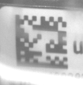
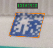
Examples
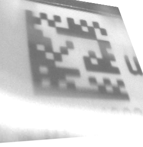
Square |
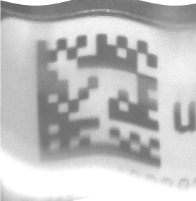
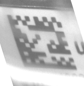
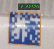
Slanted |
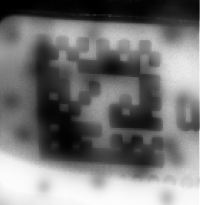
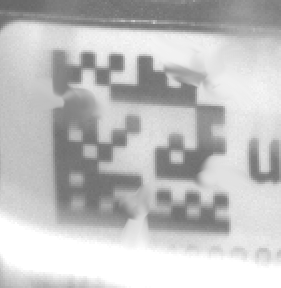
Reflection |
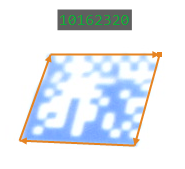
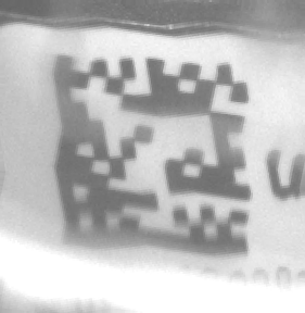
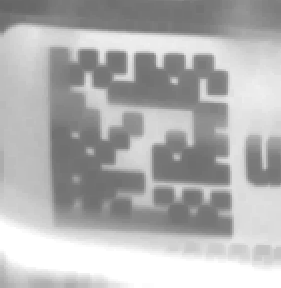
Overexposure |
Remarks
For maximum reliability of reading Data Matrix codes we recommend making sure that the image fulfills the following standard requirements:
- Module size should be at least 4.0 pixels. It is possible to read codes with modules as low as 1.25 pixels, but this comes with no guarantee and is highly dependent on the image and printing quality.
- Gaps between dot-printed marks should be not bigger than 50% of the module size, but the less the better.
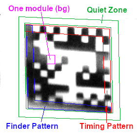
- There should be an empty space around the code ("quiet zone"). It should have the width at least equal to the module size. Contamination, additional print or shadows in this area is the most frequent source of reduced reliability.
- Finder Pattern slant (angular deviation from 90 degrees) should not be greater than 30 degrees.
For explanation of the used terminology, please refer to the below picture:
Complexity Level
This filter is available on Basic Complexity Level.
Filter Group
This filter is member of ReadDataMatrixCodes filter group.
See Also
- ReadMultipleDataMatrixCodes – Detects and recognizes several Data Matrix codes in one image.