You are here: Start » Filter Reference » Computer Vision » 1D Edge Detection » ScanSingleEdge (ScanEdges Single)
| Module: | MetrologyBasic |
|---|
Locates the strongest transition between dark and bright pixels along a given path (without a scan map).
Applications
| Name | Type | Range | Description | |
|---|---|---|---|---|
 |
inImage | Image | Input image | |
 |
inScanPath | Path | Path along which the scan is performed | |
 |
inScanPathAlignment | CoordinateSystem2D* | Adjusts the scan path to the position of the inspected object | |
 |
inScanWidth | Integer | 1 -  |
Width of the scan field in pixels |
 |
inSamplingParams | SamplingParams | Parameters controlling the sampling process | |
 |
inEdgeScanParams | EdgeScanParams | Parameters controlling the edge extraction process | |
 |
inEdgeSelection | Selection | Selection mode of the resulting edge | |
 |
inLocalBlindness | LocalBlindness* | Defines conditions in which weaker edges can be detected in the vicinity of stronger edges | |
 |
outEdge | Edge1D? | Found edge | |
 |
outAlignedScanPath | Path | Transformed input path | |
 |
outBrightnessProfile | Profile | Extracted image profile | |
 |
outResponseProfile | Profile | Profile of the edge (derivative) operator response | |
 |
diagSamplingPoints | PathArray | Array of paths each one containing the sampling points that contributes to a single value of the extracted profile | |
 |
diagSamplingStep | Real | Used distance between consecutive sampling points on the scan path | |
Description
The operation scans the image along inScanPath and locates the strongest edge perpendicular to the path. If the strongest edge is weaker than inEdgeScanParams.minMagnitude then the outputs are set to NIL.
The optional parameter inScanPathAlignment defines a transform to be performed on the inScanPath so that the actual scan path (outAlignedScanPath) is adjusted to the position of the object, typically detected by one of Template Matching filters.
Hints
- Connect an input image to the inImage input.
- Create inScanPath which is more or less perpendicular to the edge you want to detect. It should be long enough to anticipate all possible edge locations.
- Define inEdgeScanParams.EdgeTransition to detect a particular edge type, and only that type.
- Use a local coordinate system connected to inScanPathAlignment to automatically adjust the measurement to variable object position (optional).
- If the noise level is high, try increasing inScanWidth and/or inEdgeScanParams.SmoothingStdDev.
- If no edge is found, try decreasing inEdgeScanParams.MinMagnitude. Verify this with the values on the outResponseProfile output.
- If consecutive edges are closer than 6 pixels apart, change inEdgeScanParams.ProfileInterpolation to Quadratic3.
Examples
 |
 |
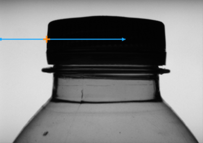
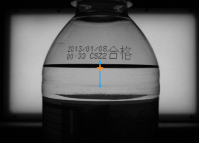
ScanSingleEdge locates the strongest edge across inScanPath.
Remarks
Read more about Local Coordinate Systems in Machine Vision Guide: Local Coordinate Systems.
This filter is a part of the 1D Edge Detection toolset. For a comprehensive introduction to this technique please refer to 1D Edge Detection and 1D Edge Detection - Subpixel Precision chapters of our Machine Vision Guide.
Hardware Acceleration
This operation is optimized for SSE2 technology for pixels of type: UINT8.
This operation is optimized for AVX2 technology for pixels of type: UINT8.
This operation is optimized for NEON technology for pixels of type: UINT8.
This operation supports automatic parallelization for multicore and multiprocessor systems.
Complexity Level
This filter is available on Basic Complexity Level.
Filter Group
This filter is member of ScanEdges filter group visible as Single.
See Also
- ScanMultipleEdges – Locates multiple transitions between dark and bright pixels along a given path (without a scan map).
- ScanExactlyNEdges – Locates a specified number of the strongest transitions between dark and bright pixels along a given path (without a scan map).
- ScanSingleEdge – Locates the strongest transition between dark and bright pixels along a given path (without a scan map).

 Basic
Basic