
You are here: Start » Program Examples » Capsules
Capsules
Aim
The task is to inspect a quality of capsules and create a simple HMI. The following defects should be detected: black spots on the surface of capsule and deformations of its shape.
Input
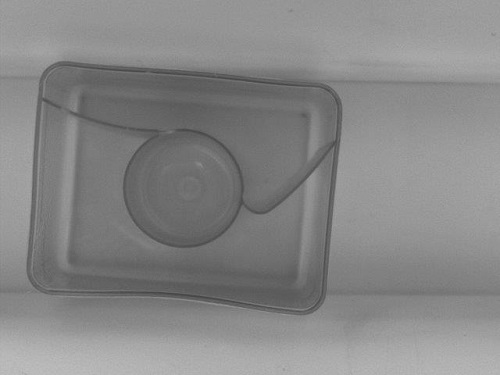
An image of a single capsule.
Output
HMI containing an image with marked defects.
Hints
To detect black spots on the capsule surface, use Blob Analysis technique, which is the fastest and the simplest way to accomplish this task. To detect shape deformations you can create a path around the undamaged capsule, which is path model, and compare it with paths bounding consecutive capsules.
Labeling connections is explained in this article.
Solution (AVS)
-
In Workspace Explorer open workspace Examples and in Film strip window select Capsule dataset. Drag the Image channel to the ACQUIRE section.
-
Create the Step macrofilter DetectBlackSpots and create the input of type Image. Place it in the PROCESS section.
-
As spots are much darker than the background, add the ThresholdToRegion filter. Set the inMinValue to 0 and the inMaxValue to 50.
-
Add the SplitRegionIntoBlobs filter to split the detected region into array of regions corresponding to each stain.
-
Right-click on the outBlobs, select "Property Outputs" and choose IsArrayEmpty from the list. The outBlobs.IsArrayEmpty output indicates whether the size of the array equals zero.
-
Drag the outBlobs.IsArrayEmpty and drop it on the Macrofilter Outputs block to create an output of the same data type. Name it outIsCorrect.
-
Add the RegionMassCenter filter and connect it with the outBlobs to find the center of each stain.
-
To create circles around stains, add the CreateCircle filter and connect its inPoint input with the outMassCenter. Set its inRadius to 20.
-
To draw the result on the image, add the DrawCircles_SingleColor filter. Set the inColor to red and the inDrawingStyle.Thickness to 2.5.
-
Create an output outBlackSpotsImage and connect it with the output of the DrawCircles_SingleColor filter.
-
Create the Step macrofilter FindCapsuleRegion which is responsible for finding the region of capsule. Create its input of type Image.
-
Add the ThresholdToRegion_Dynamic filter to create region containing dark edges. Set both the inRadiusX and the inRadiusY to 8. Set also the inMaxRelativeValue to -4.
-
Add the CloseRegion filter and set the inKernel to Cross, also set both the inRadiusX and the inRadiusY to 2.
-
Add the FillRegionHoles filter to obtain the extended region, which contains all the pixels previously lying in its holes.
-
Add the OpenRegion filter to perform a morphological opening, hence noises are removed.
-
Add the MakeRegionConditional to compute region area and check whether it is in the specified range. Set the inMinimum to 100000 and the inMaximum to 125000.
-
Create an output outRegionOrNothing and connect it with the MakeRegionConditional's output.
-
Create the Step macrofilter FindCapsuleShape and create inputs of types Image and Region. This macrofilter is responsible for finding the contour of the capsule.
-
Add the RegionConvexHull filter and connect its inRegion input with the inRegion input of the macrofilter.
-
Add the RegionContours filter and connect its input with the outRegion of the previous filter. It computes an array of closed paths corresponding to the contours of the input region.
-
Add the GetMaximumPath filter to get the path corresponding to the capsule outline. Connect its input with the output of the RegionContours.
-
Add the ConvertToEquidistantPath filter and connect its input with the output of the previous filter. Set the inStep input to 5.
-
Add the SmoothPath_Gauss filter to smooth the output of the ConvertToEquidistantPath. Set the inStdDev input to 2.
-
Add the FitPathToEdges filter and connect the inImage with the inImage input of the macrofilter.
-
Right-click on the inFittingField and select Expand Structure Fields.
-
Connect the inFittingField.Axis with the output of the SmoothPath_Gauss filter.
-
Set the following parameters of the FitPathToEdges:
- the inFittingField.Width to 50,
- the inScanWidth to 3,
- the inEdgeScanParams.SmoothingStdDev to 1,
- the inEdgeScanParams.MinMagnitude to 2,
- the inMaxInterpolationLength to 20,
- the inMaxDeviationDelta to 1.
-
Add the InflatePath filter to enlarge a path so that it is corresponding to the outer outline of the capsule. Connect the inPath with the outPath of the FitPathToEdges.
-
Drag the outPath of the InflatePath filter and drop it on the Macrofilter Outputs block to create an output of the same type. Name it outShapeOrNothing.
-
The task of macrofilters FindCapsuleRegion and FindCapsuleShape was to extract the contour of the capsule. The next step is to create Step macrofilter DetectDeformations. In this filter you will be computing the distance between the outShapeOrNothing path and the model path. If the distance is higher than specified, the capsule is damaged.
-
Create the following inputs: inImage of type Image, inShape of type Path and inBendErrorThreshold of type Real.
-
Right-click on the inShape input, select "Property Outputs" and choose Points from the list to get access to the points of the capsule outline.
-
Add the FitPathToPath filter and connect its inReferencePath input with input of the macrofilter. Set the following parameters:
- the inIterations to 3,
- the inFirstShift to 1,
- the inFirstRotation to 3.
-
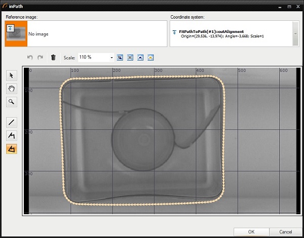
Click the "..." button at the inPath input to open the GUI for creating path model.
- Select the FitPathToPath(#1)::outAlignment coordinate system.
- Create a closed path around the capsule.
-
To compute the distance between paths, add the PathToPathDistanceProfile filter and connect its inPath1 with input of the macrofilter and the inPath2 with the output of the FitPathToPath filter.
-
Add the ClassifyByRange filter to divide the input array into three output arrays, depending on the distance between points of the paths. You should be interested in the array of points which distance to a model path is higher than specified maximum distance. Connect the following ports:
- the inArray input with the inShape.Points[].
- the inValues input with the outDistances.
- the inMaximum input with input of the macrofilter inBendErrorThreshold.
-
Right-click on the outHigher, select "Property Outputs" and select IsArrayEmpty from the list.
-
Create the macrofilter's outIsCorrect output and connect it with the IsArrayEmpty output.
-
To draw the model path on the image, add the DrawPaths_SingleColor filter and connect its inPaths input with the outPath. Set the following properties: the inColor to white, the inDrawingStyle.PointShape to Circle, the inDrawingStyle.PointSize to 3.
-
To draw the parts of the contour, where capsule is deformed, add the CreateCircle filter and connect its inPoint input with the outHigher. Then add the DrawCircles_SingleColor filter and connect its input with the outCircle.
-
Create the macrofilter's DeformationsImage output and connect it with the output image.
-
Create a Variant macrofilter PresentResultsOrInfo with the forking port inResultImage of conditional type Image?.
- In the variant Nil add the DrawStrings_SingleColor filter. Connect its inImage input with the inInputImage input of the macrofilter.
- Specify the string to be drawn, by setting the inString to Capsule damaged or not present.
- Create the macrofilter's outImage output and connect it the output of the DrawStrings_SingleColor filter.
-
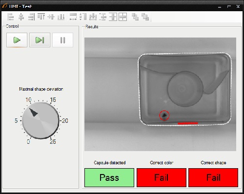
Program is finished, now you can design your HMI:
- Add the GroupBox container available in the Containers category of the HMI Controls and set its Text property to Control*.
- Add another GroupBox container and set its Text property to Results.
-
In the Control GroupBox:
- Add the ProgramControlBox control available in the Controls category to allow an user to control program execution.
- To set the maximal shape deviation, add the Knob control and connect its outValue output with the inBendErrorThreshold input of the DetectDeformations macrofilter.
-
In Results GroupBox:
- Add the VideoBox control from the Video Box category and connect its inImage input with output of the PresentResultsOrInfo macrofilter.
- Add the PassFailIndicator control and connect its inValue inputs with the outShapeOrNothing.IsNil.Not output. To make this output visible right-click on the outShapeOrNothing and select IsNil.Not. This control shows whether the capsule has been detected.
- Add the PassFailIndicator control and connect its inValue inputs with the outIsCorrect output of the DetectBlackSpots. This control shows whether there are no black spots on the capsule's surface.
- Add the PassFailIndicator control and connect its inValue inputs with the outIsCorrect output of the DetectDeformations. This control shows whether shape of the capsule is correct.
Macrofilter Main

Macrofilter FindCapsuleRegion

Macrofilter DetectBlackSpots

Macrofilter FindCapsuleShape

Macrofilter DetectDeformations

Macrofilter PresentResultsOrInfo(default)

Macrofilter PresentResultsOrInfo(Nil)

Further Readings
- Blob Analysis - Article presents detailed information about the Blob Analysis technique.
- Shape Fitting - This article presents usage of the Shape Fitting technique.