You are here: Start » Application Notes » Testing Digital Outputs of a GigEVision Camera
Testing Digital Outputs of a GigEVision Camera
Purpose and equipment
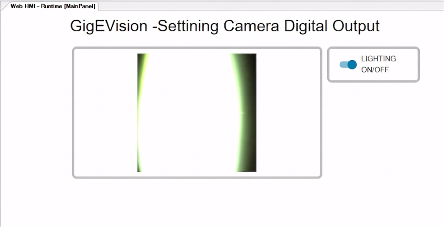
The aim of this document is to demonstrate how to control external lighting using the digital output of a GigE Vision camera in Aurora Vision Studio. The application features a WebHMI interface with a switch that allows the user to manually change the state of the camera's output pin, which in turn turns the connected light on or off.
Required equipment:
- Zebra CV60 Area Scan Camera
- EFFI-FLEX-15 LED Barlight with M12 Power - 4 pins connector
- 24V DC Power Supply
- PC with Aurora Vision Studio (version 5.7 used)
Hardware connection
PC and camera - Ethernet connection
- Ensure that both the PC network interface card (NIC) and the GigE Vision camera are configured to operate within the same subnet. In this application note, a single network is configured. Devices connected to this network have addresses 192.168.10.XXX, where XXX stands for a number from 1 to 254, unique for every device/port connected.
- If the PC is equipped with PoE ports, the camera can be connected directly to one of them. If the PC does not support PoE, the Ethernet connection from the camera to the network card port on the PC must pass through an external PoE Injector.
Electrical circuit
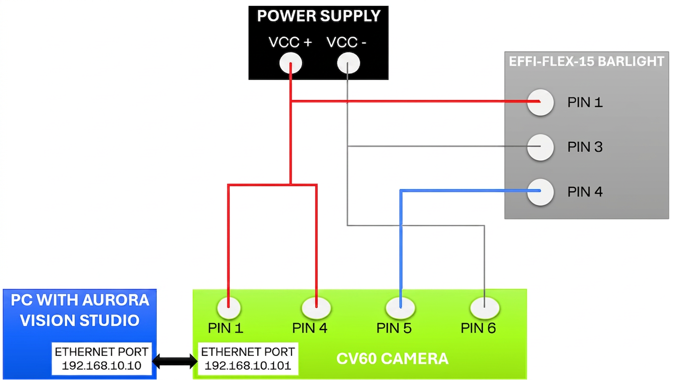
To allow the camera to trigger the external lighting successfully, the electrical wiring must be configured as follows:
- The Supply Voltage (VCC, 24V) - connect in parallel to:
- Pin 1 (Main Power and I/O Reference) and Pin 4 (Opto Out+) of the CV60 camera
- Pin 1 of the EFFI-FLEX-15 LED Barlight (Power)
- Signal Connection - connect Pin 5 of the camera (Opto Out-) directly to Pin 4 of the barlight (Pin) to completes the switching circuit.
- Power Supply Ground (VCC-) - connect to:
- Pin 6 of the camera (Ground)
- Pin 3 of the barlight (Ground)
Configuring Aurora Vision Studio application
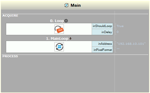
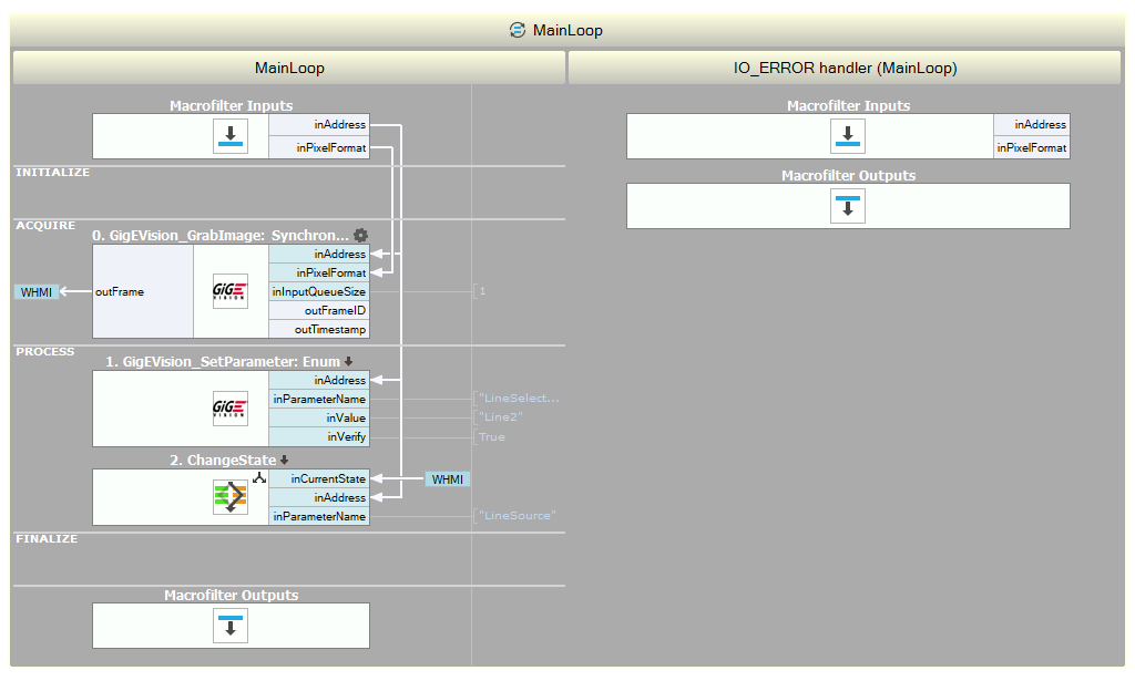
- Inside the ACQUIRE section of the Main macrofilter, add the Loop filter with default settings.
- Create a new task named MainLoop and put it in the PROCESS section of the Main macrofilter.
- Inside the MainLoop, add the GigEVision_GrabImage filter to the ACQUIRE section.
- Drag and drop the inAddress and inPixelFormat inputs from the added filter to the Macrofilter Inputs block.
- Go back to the Main macrofilter.
- Set the inAddress value of the MainLoop macrofilter to 192.168.10.101.
- Go back to the MainLoop macrofilter.
- Inside the PROCESS section, add the GigEVision_SetEnumParameter filter. Set the parameters as below:
- inParameterName: LineSelector
- inValue: Line2
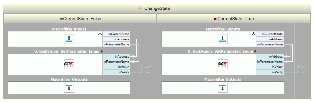
- Create a new variant macrofilter named ChangeState with the fork port inCurrentState of type bool.
- Drag and drop the inAddress output from the Macrofilter Inputs block to the ChangeState macrofilter.
- Inside the ChangeState variant macrofilter:
- False: add the GigEVision_SetEnumParameter filter. Drag and drop its inParameterName input to the Macrofilter Inputs block. Set the inValue parameter to Low.
- True: add the GigEVision_SetEnumParameter filter. Connect its inParameterName input to the inParameterName input from the Macrofilter Inputs block. Set the inValue parameter to High.
- Go back to the MainLoop macrofilter.
- Create a WebHMI panel that contains the PictureBox and the Switch controls. You can use one of the WebHMI official templates.
- Connect the PictureBox input to the outFrame output of the GigEVision_GrabImage filter.
- Connect the Switch output to the inCurrentState input of the ChangeState macrofilter.
- Add the IO_ERROR handler to the MainLoop macrofilter.
The final program should look like this:
Results
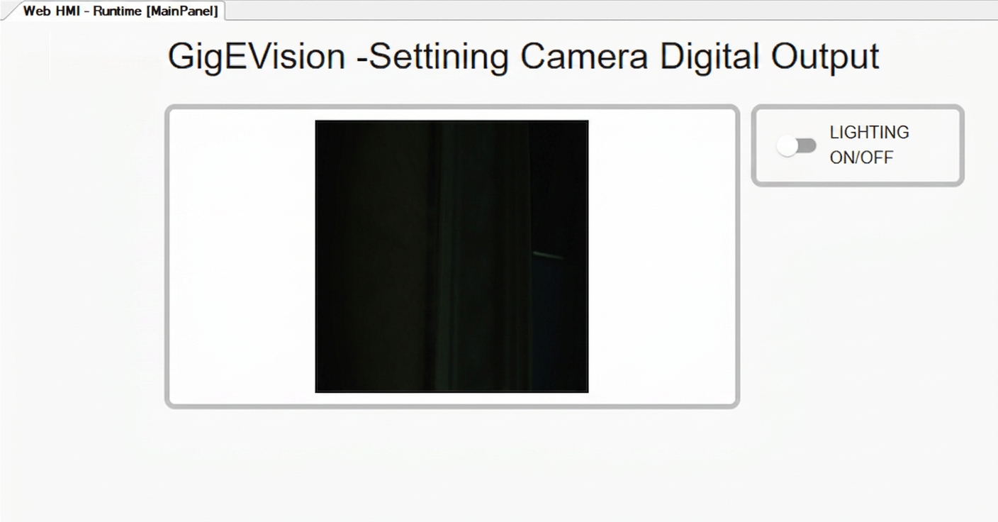
The lighting is off:
The lighting is on: