
You are here: Start » Function Reference » Computer Vision » Shape Fitting » FitPathToStripe
FitPathToStripe
| Header: | AVL.h |
|---|---|
| Namespace: | avl |
| Module: | MetrologyPro |
Performs a series of 1D stripe detections and creates a path from the detected points.
Applications: Tracing of a stripe, whose rough location and shape is known beforehand.
Syntax
void avl::FitPathToStripe
(
	const avl::Image& inImage,
	const avl::PathFittingMap& inFittingMap,
	const StripeScanParams& inStripeScanParams,
	avl::Selection::Type inStripeSelection,
	atl::Optional<const avl::LocalBlindness&> inLocalBlindness,
	atl::Optional<int> inMaxInterpolationLength,
	atl::Optional<float> inMaxDeviationDelta,
	float inMaxIncompleteness,
	atl::Conditional<avl::Path>& outPath,
	atl::Conditional<avl::Path>& outLeftPath,
	atl::Conditional<avl::Path>& outRightPath,
	atl::Array<atl::Conditional<avl::Stripe1D>>& outStripes,
	atl::Optional<atl::Conditional<avl::Profile>&> outDeviationProfile = atl::NIL,
	atl::Optional<atl::Array<avl::Profile>&> outBrightnessProfiles = atl::NIL,
	atl::Optional<atl::Array<avl::Profile>&> outResponseProfiles = atl::NIL
)
Parameters
| Name | Type | Range | Default | Description | |
|---|---|---|---|---|---|
 |
inImage | const Image& | Image to fit the path to | ||
|
inFittingMap | const PathFittingMap& | Input fitting map | ||
|
inStripeScanParams | const StripeScanParams& | Parameters controlling the stripe extraction process | ||
|
inStripeSelection | Selection::Type | Selection::Best | Selection mode of stripe | |
|
inLocalBlindness | Optional<const LocalBlindness&> | NIL | Defines conditions in which weaker edges can be detected in the vicinity of stronger edges | |
|
inMaxInterpolationLength | Optional<int> | 0 -  |
NIL | Maximal number of consecutive points not found |
|
inMaxDeviationDelta | Optional<float> | 0.0 - |
NIL | Maximal difference between deviations of consecutive path points |
|
inMaxIncompleteness | float | 0.0 - 0.999 | 0.1f | Maximal fraction of stripe points not found |
 |
outPath | Conditional<Path>& | Fitted path in the middle of found stripe | ||
|
outLeftPath | Conditional<Path>& | Fitted left path | ||
|
outRightPath | Conditional<Path>& | Fitted right path | ||
|
outStripes | Array<Conditional<Stripe1D>>& | Found stripes | ||
|
outDeviationProfile | Optional<Conditional<Profile>&> | NIL | Profile of distances between the actual path points and the corresponding reference path points | |
|
outBrightnessProfiles | Optional<Array<Profile>&> | NIL | Extracted image profiles | |
|
outResponseProfiles | Optional<Array<Profile>&> | NIL | Profiles of the edge (derivative) operator response |
Optional Outputs
The computation of following outputs can be switched off by passing value atl::NIL to these parameters: outDeviationProfile, outBrightnessProfiles, outResponseProfiles.
Read more about Optional Outputs.
Description
The operation tries to fit a given path to stripe present in the inImage image. Internally, it performs a series of scans with the ScanSingleStripe filter using inFittingMap previously generated from the object being fitted. The found points are then used to determine the actual position of the path in the image. Only inMaxIncompleteness fraction of these scans may fail. If the fitting according to the given parameters is not possible, outPath is set to Nil.
There are also another parameters that control the path fitting process. The inMaxDeviationDelta parameter defines the maximal allowed difference between deviations of consecutive points from the input path points. If some of the scans fail or if some of found points are classified to be wrong according to another control parameters, output path points corresponding to them are interpolated depending on points in their nearest vicinity. No more than inMaxInterpolationLength consecutive points can be interpolated. The exception to this behavior are points which were not found on both ends of the input path. Those are not part of the result at all.
Hints
- Connect an input image to the inImage input.
- Define inStripeScanParams.StripePolarity to detect a particular stripe type, and only that type.
- Adjust inStripeScanParams.MinStripeWidth and inStripeScanParams.MaxStripeWidth to the expected thickness of the stripe (in pixels).
- If no or too few stripe points are found, try decreasing inStripeScanParams.MinMagnitude.
- If some of the scans may fail, set the inMaxIncompleteness input accordingly.
- Use the outStripes outputs to visualize the scanning results.
Examples
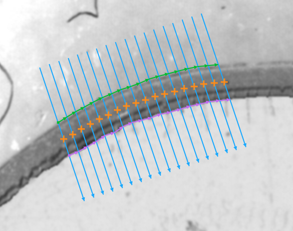
Fitting a path to a dark stripe
(inStripeScanParams.SmoothingStdDev = 2.0, inStripeScanParams.MinStripeWidth = 15.0, inStripeScanParams.StripePolarity = Dark).
Remarks
Read more about Local Coordinate Systems in Machine Vision Guide: Local Coordinate Systems.
This filter is a part of the Shape Fitting toolset. To read more about this technique, one can refer to the Shape Fitting chapter of our Machine Vision Guide
Hardware Acceleration
This operation supports automatic parallelization for multicore and multiprocessor systems.
See Also
- CreatePathFittingMap – Precomputes a data object that is required for fast path fitting on images.
- FitPathToEdges – Performs a series of 1D edge detections and creates a path from the detected points.
- FitPathToRidges – Performs a series of 1D ridge detections and creates a path from the detected points.
- FitPathToStripe_Direct – Performs a series of 1D stripe detections and creates a path from the detected points.