
You are here: Start » Filter Reference » Computer Vision » Line Finder » FindMultipleLines (FindLines Multiple)
FindMultipleLines (FindLines Multiple)
 Basic
Basic| Module: | MetrologyPro |
|---|
Finds multiple straight lines within a rectangular scan field, ordered from highest-scoring to lowest.
Applications
| Name | Type | Range | Description | |
|---|---|---|---|---|
 |
inImage | Image | Input image | |
|
inScanField | SegmentScanField | Region where the scans are performed | |
|
inScanFieldAlignment | CoordinateSystem2D* | ||
|
inScanWidth | Integer | 1 -  |
How many pixels are sampled perpendicularly at each scan line's positions |
|
inScanStep | Integer | 1 - |
Pixel distance between the centers of consecutive scan lines |
|
inScanLimit | Integer | 1 - |
Maximum number of scan lines |
|
inEdgeScanParams | EdgeScanParams | Parameters of 1D edge detection along a single scan line | |
|
inPointBlindness | Real | 0.0 - 1.0 | Defines a threshold for rejecting edge points that are weaker than a certain portion of the strongest edge point |
|
inMaxSlant | Real | 0.0 - 45.0 | Maximum angle deviation of the resulting line from 90 degrees to the scan axis |
|
inMinLength | Real | 0.0 - |
Minimum length of the resulting line |
|
inMaxGap | Real | 0.0 - |
Maximum gap within a resulting line |
|
inMinPointCount | Integer | 2 - |
Minimum number of edge points that a resulting line must contain (otherwise it is rejected) |
|
inLineSelection | LineSelection | Selection criteria for edge lines | |
|
inLineBlindness | Real | 0.0 - 1.0 | Defines a threshold for rejecting entire lines that are weaker than a certain portion of the strongest line |
|
inEdgeMeasure | EdgeMeasure | Several options for measuring a single edge point | |
|
inLineFinderMethod | LineFinderMethod | Several alternative algorithms for finding lines within the detected cloud of edge points | |
|
inMaxPointDeviation | Real | 0.0 - |
Maximum pixel distance between a detected line and its supporting edge points |
|
inMaxTurnAngle | Real | 0.0 - 90.0 | Maximum turn angle at any interior vertex of the line path |
|
inOutlierSuppression | LineMEstimator* | A method for removing outlying points | |
|
inRefineEndpoints | Bool | Turns on a method for refining the length of the detected line | |
|
inMaxCount | Integer* | 1 - |
Maximum number of lines to return |
 |
outLines | Segment2DArray | ||
|
outLineStrengths | RealArray | ||
|
outResponseProfiles | ProfileArray | Edge response profiles, one per scan line | |
|
outAlignedScanField | SegmentScanField | ||
|
outSelectedPoints | Point2DArrayArray | Lists of points associated with each returned line | |
 |
diagScanLines | Segment2DArray | Positions of the scan lines placed within the scan field | |
|
diagCandidatePoints | Point2DArray | Edge points detected on the scan lines, after inPointBlindness filtering | |
Description
The operation finds all straight lines within the inScanField and returns them ordered from the highest-scoring to the lowest. It works like FindSingleLine, but iterates the selection: once a line is accepted, its supporting candidate points are excluded from the competition for subsequent lines, so the results are non-overlapping. Up to inMaxCount lines are returned.
Hints
- Activate diagCandidatePoints and diagScanLines during development to verify that candidates appear on the right scan lines before adjusting higher-level parameters.
- Adjust inEdgeScanParams.MinMagnitude first: a value that is too high misses real edges; too low fills the result with noise candidates.
- Increase inScanStep to speed up execution on large scan fields. Keep it small (5–10 px) when the line is short or its position varies rapidly across the field.
- inPointBlindness suppresses weak per-scan-line candidates relative to the strongest response on that line. A value of 0.3 discards candidates below 30 % of the highest value on that scan line.
- If a detected segment is shorter than the actual line, try increasing inMaxGap, widening inMaxPointDeviation.
- Set inMaxSlant to the maximum expected deviation of the line from the direction perpendicular to the scan field axis. Narrowing this range reduces false positives.
- Use inLineSelection = Fittest for the straightest line, Strongest for the highest-contrast line, and Smoothest for gently curved or slightly wavy lines.
- Connect inScanFieldAlignment to a coordinate system to automatically adapt the measurement to the object position in each frame.
- Set inMaxCount to the exact number of parallel lines expected to prevent spurious detections and unnecessary computation.
- Increase inLineBlindness to reject weak secondary lines; decrease it to include fainter candidates.
Examples
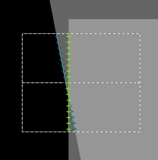
FindMultipleLines locating two intersecting lines. The dashed rectangle is the scan field, the blue and yellow dots are candidates selected for two lines, and the green lines are detected lines.
Remarks
Read more about Local Coordinate Systems in Machine Vision Guide: Local Coordinate Systems.
Hardware Acceleration
This operation supports automatic parallelization for multicore and multiprocessor systems.
Complexity Level
This filter is available on Basic Complexity Level.
Filter Group
This filter is member of FindLines filter group visible as Multiple.
See Also
- FindSingleLine – Finds a single straight line within a rectangular scan field.
