
You are here: Start » User Interface » Preparing Rectification Transform Map
Preparing Rectification Transform Map
Overview
Before you read this article, make sure you are acquainted with Camera Calibration and World Coordinates.
If you want to perform camera calibration in Adaptive Vision Studio, there two basic ways to do that. You can either use a calibration editor (plugin) or use filters (manual configuring parameters and connecting outputs with corresponding inputs). Both approaches provide you with the very same results, but the latter way allows you to control intermediate steps and outputs if they are relevant to you for some reason.
This guide will focus mainly on the first approach and show how to perform calibration with the editor step by step. To perform image rectification, the RectifyImage filter should be applied. When you click on the inRectificationMap input, the Calibration Editor will be displayed:
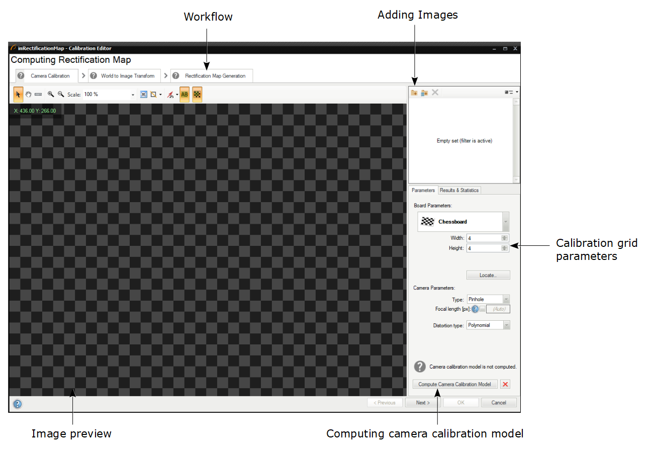
The overview of the Calibration Editor.
As you can see the editor consists of three pages:
- Camera Calibration - in which camera lens parameters are computed.
- World to Image Transform - in which perspective and transform converting real-world points to image points are computed.
- Rectification Map Generator - in which fast pixel transform is computed to get a rectified image.
Each of the pages will be individually described, but as it has been already noted, each of the pages in the Calibration Editor invokes corresponding calibration filters. The general overview is in the table below:
| Page name | Corresponding filters |
|---|---|
| Camera Calibration | |
| World to Image Transform | |
| Rectification Map Generation |
CreateRectificationMap_Advanced |
Camera Calibration Page
On the first page of the Calibration Editor you have to provide images of calibration boards, using the buttons marked in red:
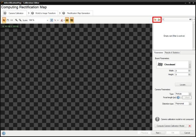
Camera Calibration Page - adding images.
Next, you have to specify board and camera parameters. There are two possible options to choose from, depending on what kind of pattern is used:
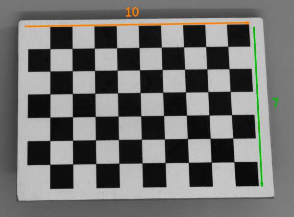
- Chessboard - where you have to define two parameters of the board: width and height, which correspond to the number of squares in horizontal and vertical directions, respectively.
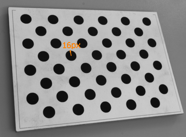
- Circles - where you have to define a single circle's radius and threshold value.
|
|
|
If you are using chessboard pattern, you have to count squares in both dimensions. In this example, the width is 10 and the height is 7. |
If you are using circle pattern, you have to measure radius of any circle. In this example, it is about 16px. |
A few distortion model types are supported. The simplest - divisional - supports most use cases and has predictable behavior even when calibration data is sparse. Higher order models can be more accurate, however, they need a much larger dataset of high quality calibration points, and are usually needed for achieving high levels of positional accuracy across the whole image - order of magnitude below 0.1 px. Of course this is only a rule of thumb, as each lens is different and there are exceptions.
Results & Statistics tab informs you about results of the calibration, especially about reprojection error, which corresponds with reprojection vectors shown in red on the preview in the picture below:
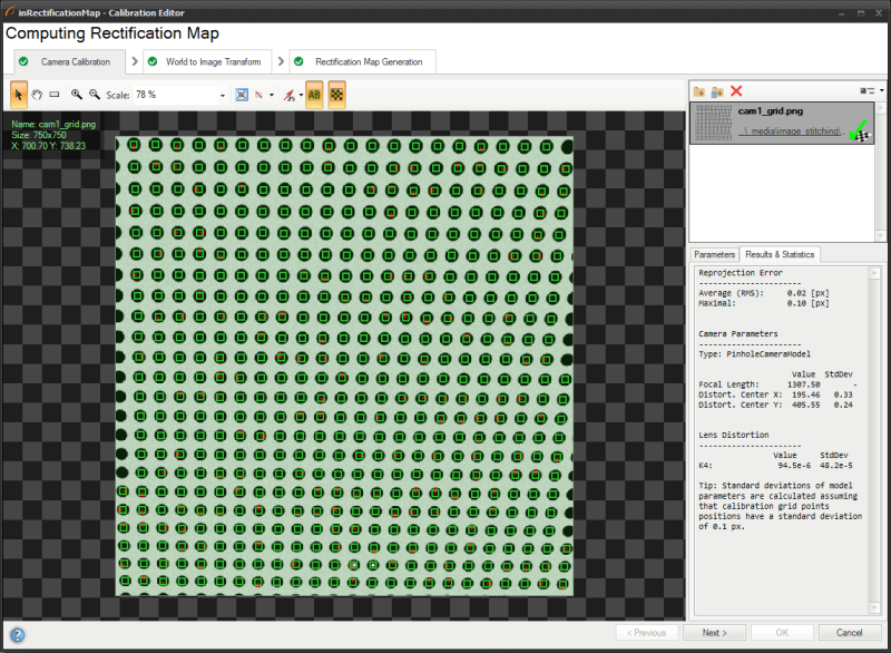 They indicate the direction towards each located point should be moved in order to deliver an immaculate grid. Additionally, there are values of Root Mean Square and Maximal error.
The tab also displays value and standard deviation for each computed camera and lens distortion parameter.
They indicate the direction towards each located point should be moved in order to deliver an immaculate grid. Additionally, there are values of Root Mean Square and Maximal error.
The tab also displays value and standard deviation for each computed camera and lens distortion parameter.
For more details, please refer to the corresponding group of filters for this page in the table above.
World to Image Transform Page
Points added to the second page are used to find transformation between real-world and image points.
World to Image Transform - overview.
First of all, in this step, you need to add images of the calibration board as well (using the very same buttons as in the previous step). Please note that in this step they have to be taken from a fixed angle in contrast to the previous step, where all of images could be taken from different angles.
In the next step you should indicate points source in either of two ways:
- By entering points manually
- By using calibration grid - in which you also have to choose between:
- Labeled grid - default and recommended in most cases.
- Offgrid origin - unrecommended, used for rather rarely seen special cases when origin and X axis are outside the grid.
After successful points location on the calibration board, you should use the spreadsheet to manually enter coordinates in world plane:
World to Image Transform - modifying points in the spreadsheet.
Points with unspecified world coordinates will have them calculated automatically based on points with specified coordinates. If there are no world coordinates entered, then algorithm will assume some default world point locations, what might produce false results. At least two grid point world coordinates are needed to uniquely determine the world plane position, rotation and spacing.
|
World to Image Transform - automatic grid spacing assumed. |
|
World to Image Transform - grid spacing calculated from world point coordinates given by the user. |
Arrows indicate which points from the calibration grid relate to corresponding rows in the spreadsheet. As you can see each row consists of coordinates in the image plane (given in pixels), coordinates in the world plane (given in mm), and error (in pixels), which means how much a point is deviated from its model location. In this case reprojection vectors, which are marked as small, red arrows, also indicate the deviation from the model.
Colors of points have their own meaning:
- Green Point - the point has been computed automatically.
- Orange Point - the point which has been selected.
- Blue Point - the point has been adjusted manually.
The Results & Statistics tab shows information about computed errors for both image and world coordinates. The output reprojection errors are useful tool for assessing the feasibility of computed solution. There are two errors in the plugin: Image (RMS) and World (RMS). The first one denotes how inaccurate the evaluation of perspective is. The latter reflects inaccuracy of labeling of grid 2D world coordinate system. They are independent, however they both influence quality of the solution, so their values should remain low.
For the details, please refer to the corresponding group of filters for this page in the table above.
Rectification Map Generator Page
Last page is used to set parameters of an image after the rectification.
First of all, you need to load images of the calibration board in the same way as in previous steps.
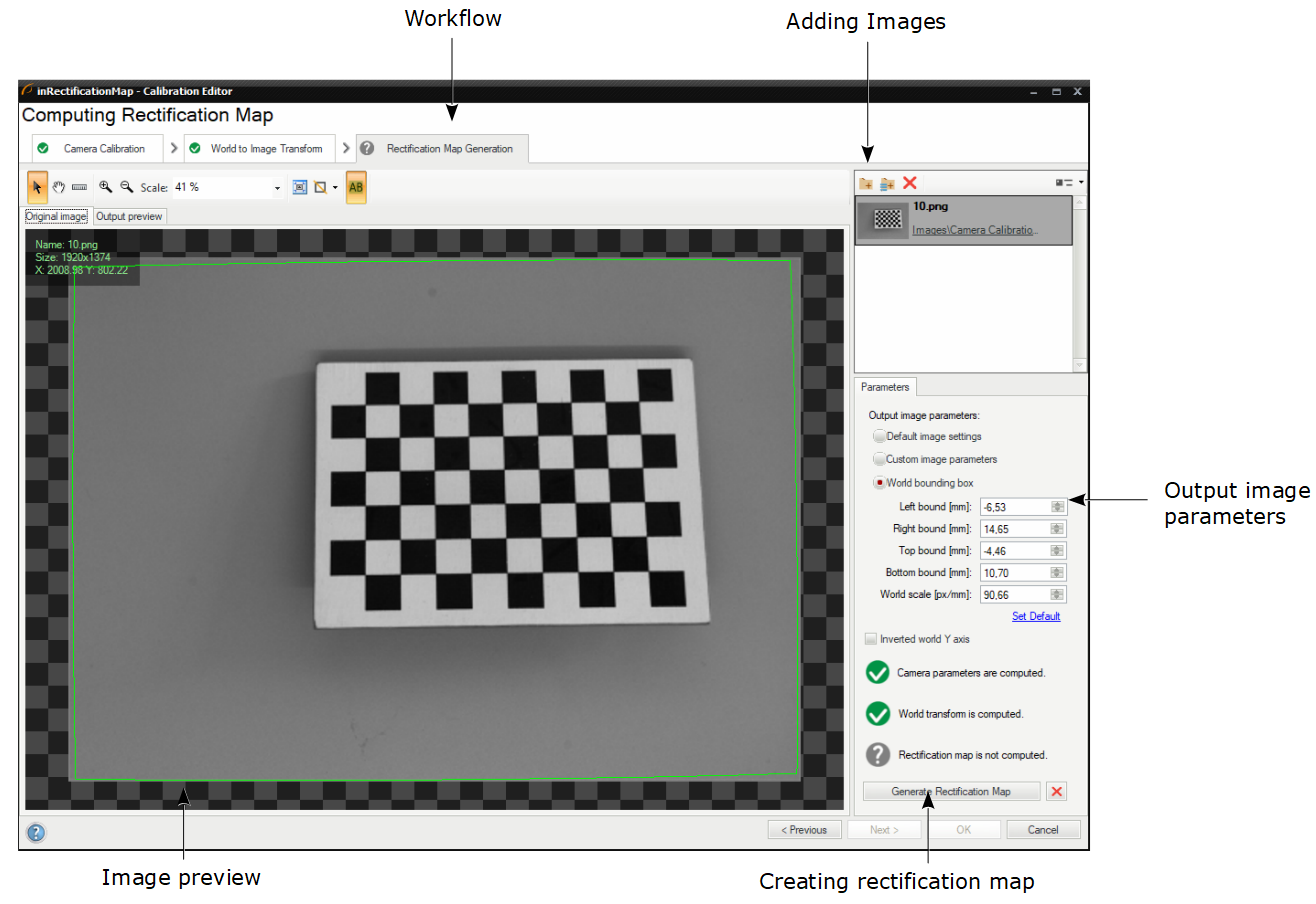
Rectification Map Generation - rectifying the image.
Next, you have to choose one of three basic options of the output image:
- Default image settings
- Custom image parameters
- World bounding box
The green frame on the preview informs you about the size and borders of the output image, and depending on what option you have chosen, you can set different parameters. Using custom parameters or world bounding box will provide you with the same rectification map, but what makes the difference is that you are working in different domains - in the first case you are operating in the image coordinates (given in pixels), whereas in the other one you are operating in the world coordinates (given in millimeters).
When you are done, you can click on the Generate Rectification Map button and assess the rectified image displayed on the preview.
For the details, please refer to the corresponding group of filters for this page in the table above.
Relation between the Calibration Editor and filters
The relation between both approaches could be presented in a form of the below graphics:
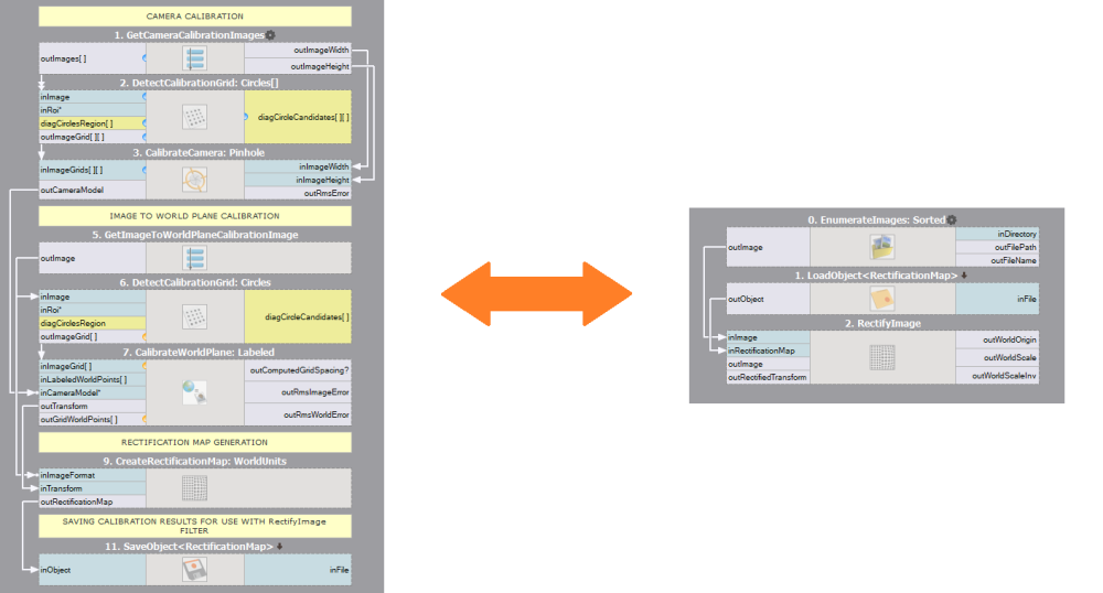
The left side presents which filters are necessary to generate a rectification map and how to save it using SaveObject. The right side presents how to load the rectification map using LoadObject and passing it to the RectifyImage filter.
This is just an exemplary set of filters which might be applied, but using specific filters depend on the calibration board and other parameters relevant to a case.
Further readings
| Previous: Creating Models for Template Matching | Next: Creating Text Segmentation Models |