
You are here: Start » Tutorial Exercises » Image Stitching (image_stitching)
Image Stitching (image_stitching)
Aim
A field of view is covered with two cameras. Create one stitched image despite significant perspective and lens distortion.
Input
Two calibration images, one for each camera.
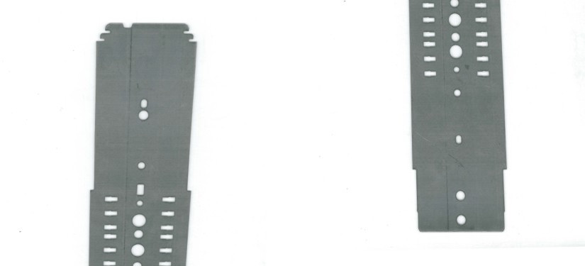
Two object images, one for each camera.
Output
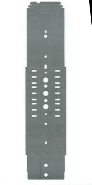
One stitched object image.
Hints
Refer to the Camera Calibration And World Coordinates section of the Machine Vision Guide for a theoretical background to fully understand this tutorial.
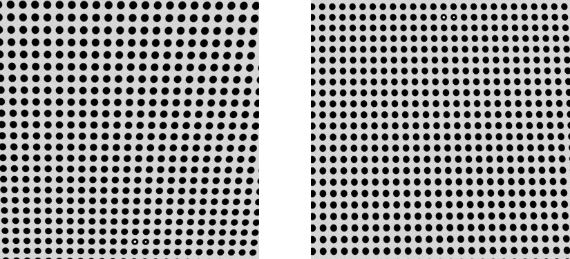
Note that the calibration grid contains a special marker - a pair of empty circles. The circle with bigger hole is the origin of the world plane, and the circle with smaller hole next to it defines the X axis direction. The grid spacing is 20mm, the first camera is responsible for area from -200mm to 200mm in X coordinate and -400mm to 0 in Y coordinate. The second camera: from -200mm to 200mm in X coordinate and 0 to 400mm in Y coordinate.
Labeling connections is explained in this article.
Solution (AVS)
-
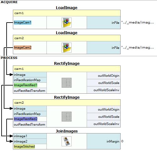
Add two images using LoadImage filters.
-
Add a RectifyImage filter for each camera.
-
For each camera, open the inRectificationMap editor:
-
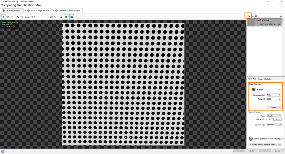
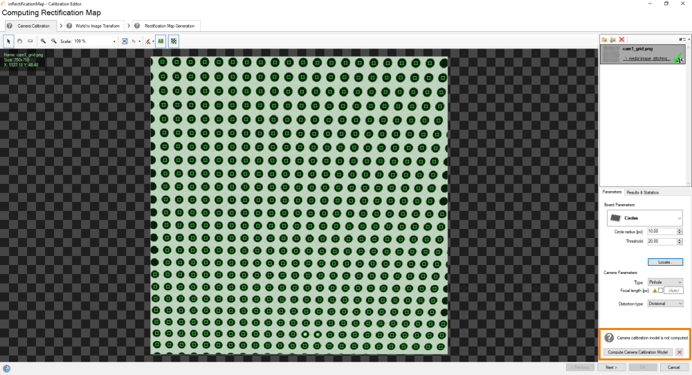
In the first step perform usual calibration of intrinsic camera parameters. Although only one grid image is available, it contains a large number of calibration points, so it should suffice. First of all, load the calibration image. Then choose board parameters as follows and click Locate:
 If the points are successfully computed, click Compute Camera Calibration Model:
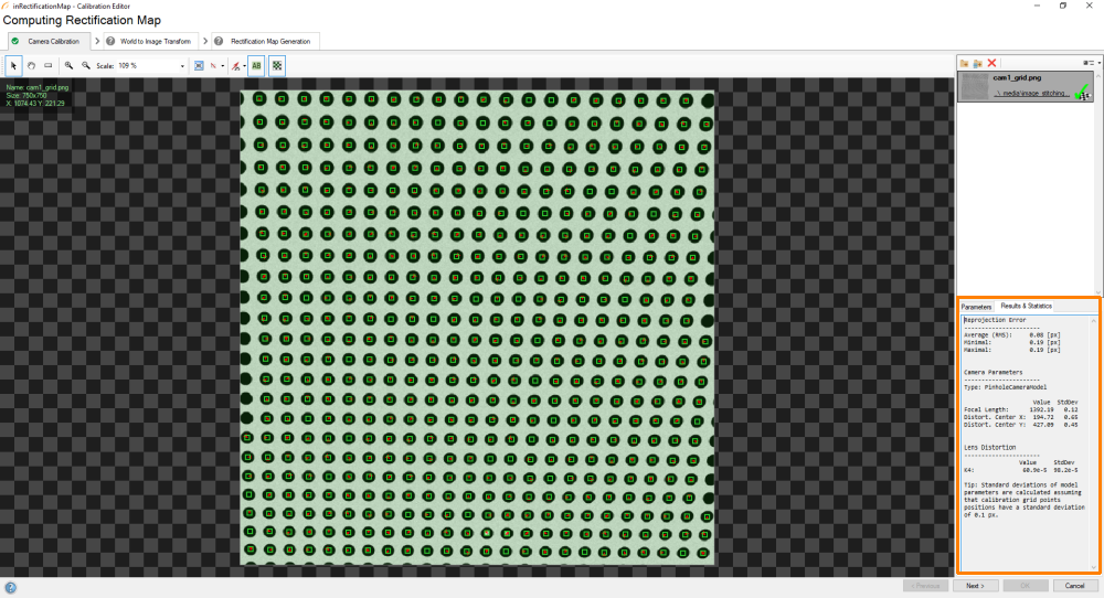
 The results window should appear:
-
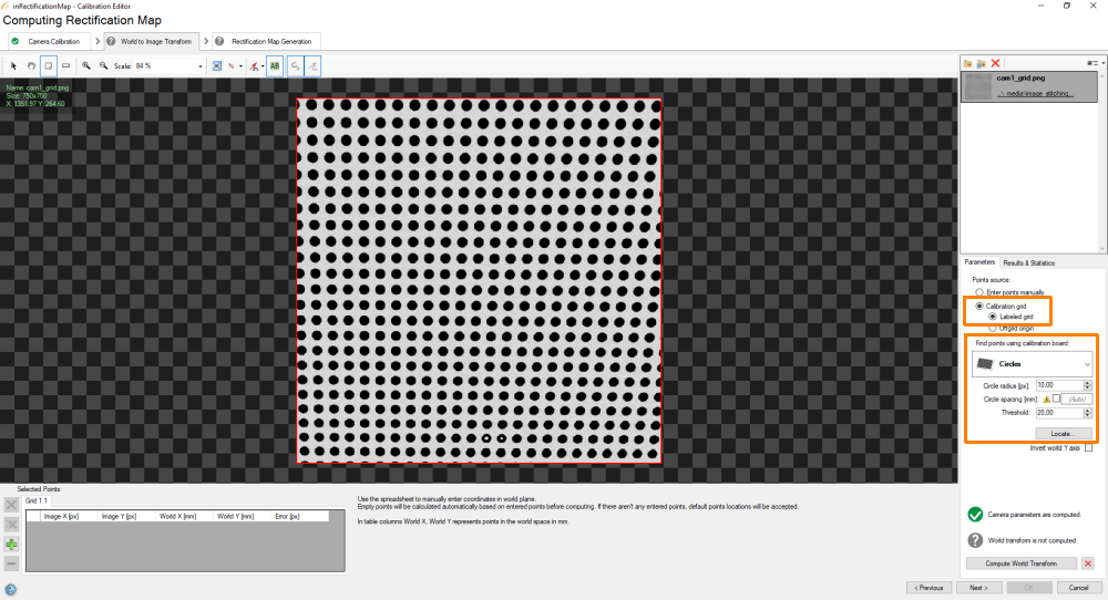
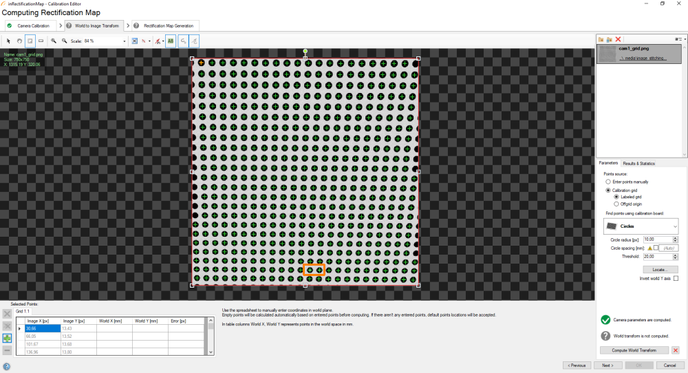
In the second step, load the same calibration image, setup the grid parameters appropriately (please, note that you have to use the Labeled grid mode) and locate the grid:
-
Once the points are located:
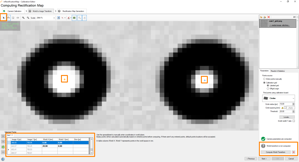
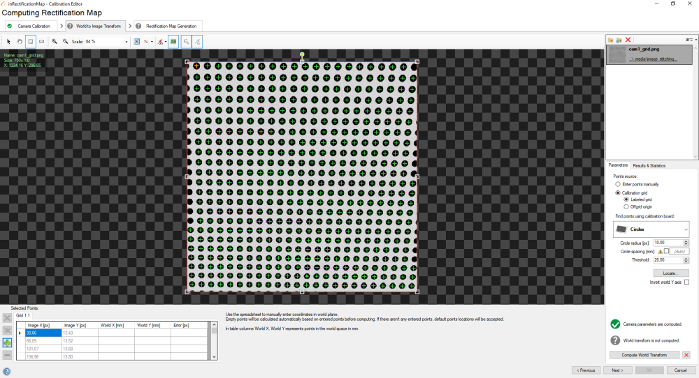 You have to determine the image to world plane transform. In order to do that, find two empty dots in the calibration grid, which would allow us to compute spacing:
-
When you have found them, use the editing tool, click on the first point and define its world coordinates (0,0). Next, click on the other point and define its world coordinates (20,0). Spacing between points should be 20mm. Once you are ready, click on the Compute World Transform button.
-
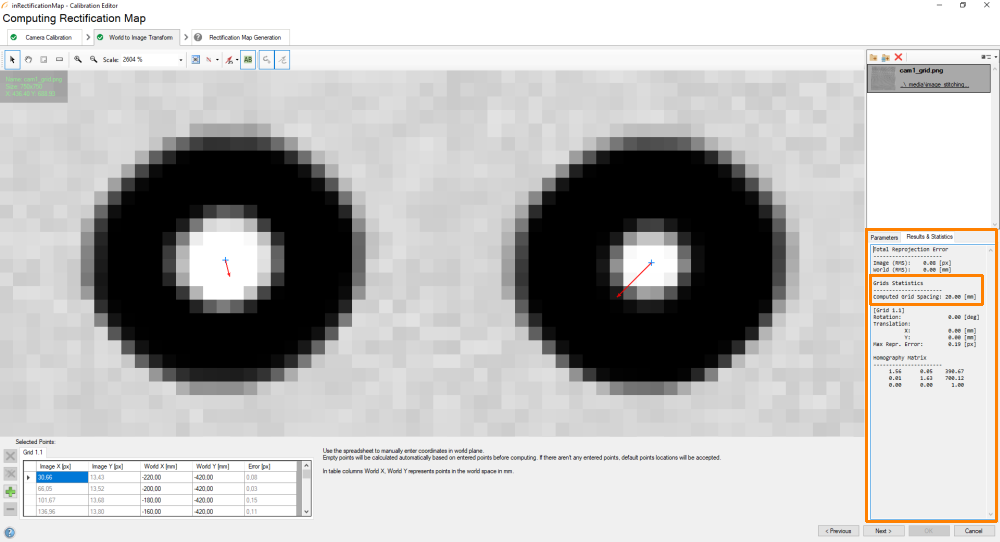
The results window should be prompted. Please, make sure that the spacing has been computed correctly (20mm):
-
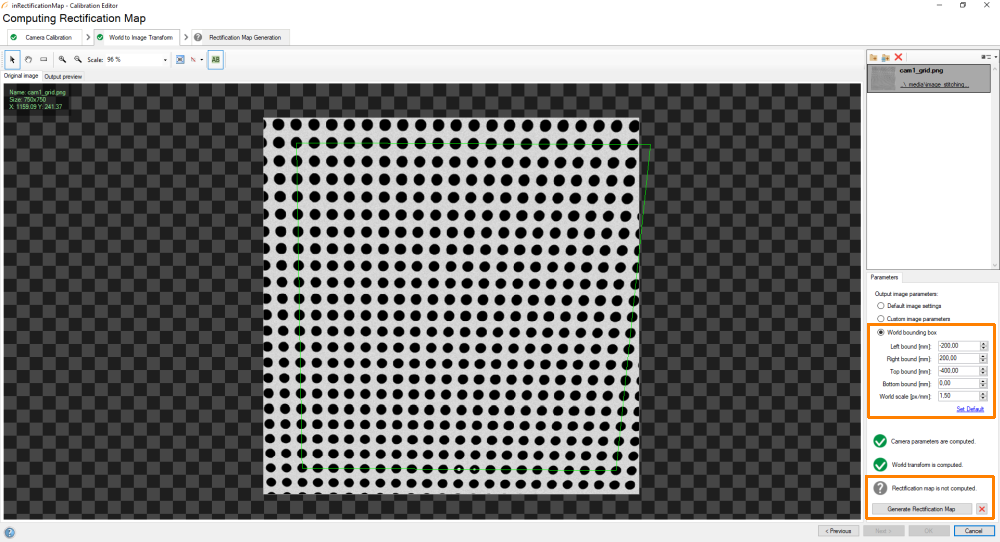
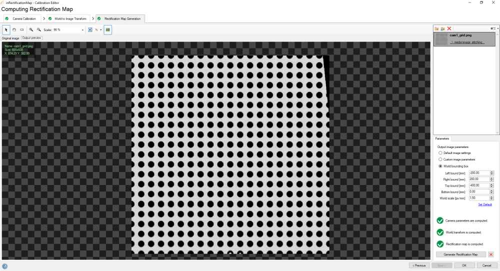
In the third step, load the same calibration image, set the "Output image parameters" to "World bounding box". Set the bounds appropriately: left bound = -200, right bound = 200, top bound = -400 (for first camera) or 0 (for second camera), bottom bound = 0 (for first camera) or 400 (for second camera). Set the world scale to 1.5 px/mm. Click on the Generate Rectification Map button:
-
As a result, you will obtain a rectified image of the calibration grid:
-
-
Join the images using the JoinImages filter. In this case, the images must be joined vertically, with the rectified image from first camera on top, and the rectified image from second camera on bottom.
Macrofilter Main
Further Readings
- Camera Calibration And World Coordinates - An introduction to camera calibration and world to image coordinate system transformations.