
You are here: Start » Technical Issues » Working with National Instruments devices
Working with National Instruments devices
Introduction
Adaptive Vision Studio allows for communication with i/o devices from National Instruments. This is done by using filters from the Hardware Support :: National Instruments category.
Working with Tasks
The entire support for National Instruments devices is based on tasks (do not confuse with Task macrofilters). A task in Adaptive Vision Studio is a single channel. Every task is associated with an ID, which is necessary for configuring tasks, reading states from inputs or writing values to device outputs.
Creating Tasks
To start working with National Instruments' devices, a task that will perform a specific operation must be created.
These filters return outTaskID, which is the identifier of a created task. Starting TasksTo start a task, filter DAQmx_StartTask should be used. Finishing Tasks
There are two ways of finishing tasks: by using the DAQmx_StopTask filter or by waiting for the entire program to finish. |
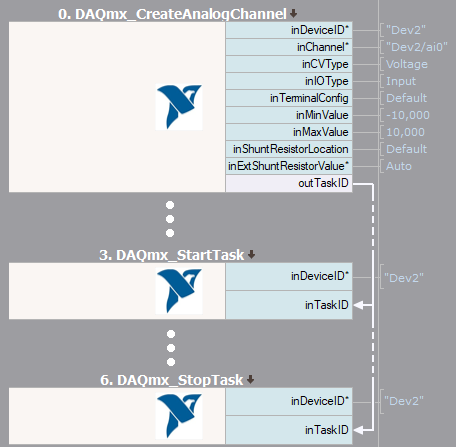
Basic scheme of program |
Reading and Writing Values
Adaptive Vision Studio provides two kinds of filters for reading and writing values. DAQmx_WriteAnalogArray, DAQmx_WriteDigitalArray and DAQmx_ReadAnalogArray, DAQmx_ReadDigitalArray, DAQmx_ReadCounterArray filters allow to work with multiple values. For reading or writing a single value, DAQmx_WriteAnalogScalar, DAQmx_WriteDigitalScalar and DAQmx_ReadAnalogScalar, DAQmx_ReadDigitalScalar, DAQmx_ReadCounterScalar filters should be used.
Configuring Tasks
After creating a task, it can be configured using the filters DAQmx_ConfigureTiming, DAQmx_ConfigAnalogEdgeTrigger or DAQmx_ConfigDigitEdgeTrigger. Note that some configuration filters should be used before the task is started.
Sample Application
The following example illustrates how to use DAQmx filters. The program shown below reads 5000 samples of voltage from analog input. However, data is acquired on rising edge of a digital signal.
|
At first, analog channel is created. In this sample, input values will be measured, so inCVType input must be set to Voltage and inIOType should be set to Input. The rest of inputs depends on used device. Afterwards, sample clock to task is assigned. inDeviceID input might be set to Auto, because it is the only one device used in this program. Other parameters could be set according to user's camera. Sample application should start acquiring data after a digital edge occurs. Because an active edge of digital signal should be rising, inTriggerEdge input must be set to Rising (for falling edge, value Falling must be chosen). Task is ready to start. Last step in presented program is to acquire multiple data from selected device. Filter DAQmx_ReadAnalogArray could be used for this. DAQmx_StopTask is not required, because this program doesn't use one channel in two different tasks. Acquired array of values might be represented e.g. as a profile (shown below). 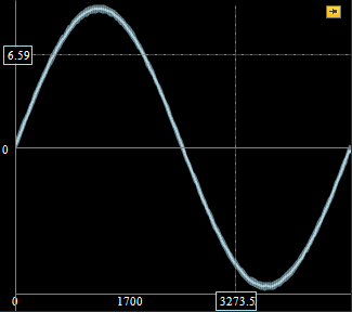
Acquired data from DAQ device |
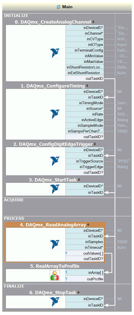
Sample application for acquiring data |
| Previous: Working with Gen TL Devices | Next: Communication with Modbus TCP devices |