
You are here: Start » Program Examples » Rubber Ring
Rubber Ring
Aim
The aim of the program is to detect improperly assembled segments of a rubber band.
Input
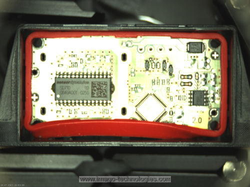
An image of a chip with an assembled rubber band around it.
Output
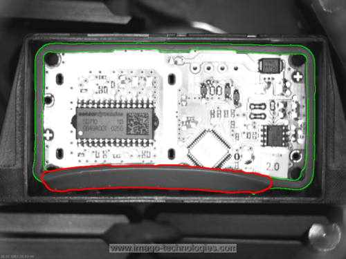
Proper and improper segments of the rubber band.
Hints
It is possible to achieve this goal in many ways. In this solution we will use Blob Analysis as it is one of the easiest approach.
Labeling connections is explained in this article.
Solution (AVS)
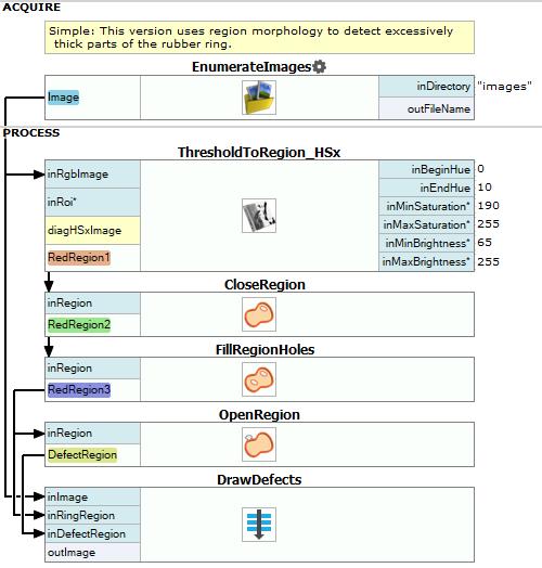
- Add the EnumerateImages filter.
- Add ThresholdToRegion_HSx and connect outImage with inRgbImage.
-
Click on the ThresholdToRegion_HSx filter and make these changes in the Properties window (in the left bottom corner):
- Set inEndHue to 10.
- Set inMinSaturation to 190.
- Set inMaxSaturation to 255.
- Set inMinBrightness to 65.
- Set inMaxBrightness to 255.
The values above were chosen based on information from the diagHSxImage diagnostic output which displays HSV values. Using the color-picker tool you should easily get these values as well. Please note that they are prompted as RGB values, but they are HSV values in fact.
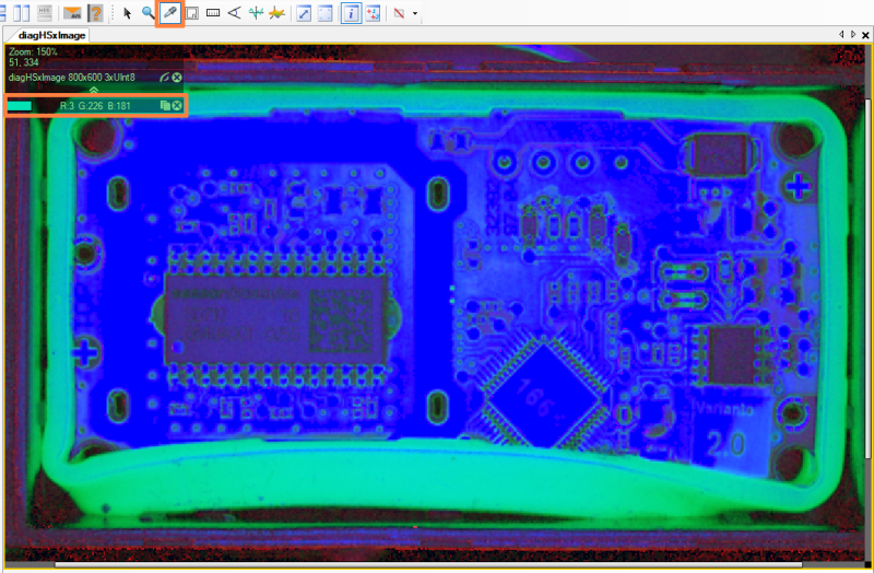
HSV values obtained with a color-picker tool.
-
Add the CloseRegion filter to close the region corresponding to the rubber ring. Connect outRegion from a previous filter with inRegion of the current one.
- Click on the CloseRegion filter. In the Properties window:
- Add the FillRegionHoles filter to fill the holes in the region. Connect outRegion to inRegion.
- Click on the FillRegionHoles filter and in Properties window set inMaxHoleArea to 10000 to avoid filling the area inside the rubber ring.
- Add the OpenRegion filter to find the bolder area of the rubber ring. Connect outRegion to inRegion.
- Click on the OpenRegion filter. In the Properties window:
- Now add a new step macrofilter, name it DrawDefects and add following inputs to it:
- Get inside newly-created macrofilter and add the RegionContours filter.
- Connect inRingRegion with inRegion. Click on the RegionContours filter and set inContourMode to PixelEdges.
- Add another RegionContours filter to get an array of closed paths corresponding to the contours of the input region and connect inErrors to its input inRegion. Set inContourMode to PixelEdges.
- Add the AverageChannels filter to get a grayscale image and connect macrofilter's inImage to inImage.
- Add the DrawPaths_SingleColor filter.
- Connect outImage to inImage.
- Connect outContours from the first RegionContours filter and connect to inPaths.
- Click on the DrawPaths_SingleColor and in Properties window make these changes:
- Set inColor to green.
- Set inDrawingStyle.Opacity to 0.75.
- Set inDrawingStyle.Thickness to 2.
- Set inDrawingStyle.PointSize to 2.
- Add another DrawPaths_SingleColor filter.
- Connect outImage from a previous filter with inImage of the current one.
- Connect outContours from the other RegionContours filter and connect to inPaths.
- Click on the DrawPaths_SingleColor filter and in Properties window make these changes:
- Set inColor to red.
- Set inDrawingStyle.Thickness to 3.
- Set inDrawingStyle.PointSize to 2.
- Connect outImage to macrofilter outputs and name it outImage.
Macrofilter Main
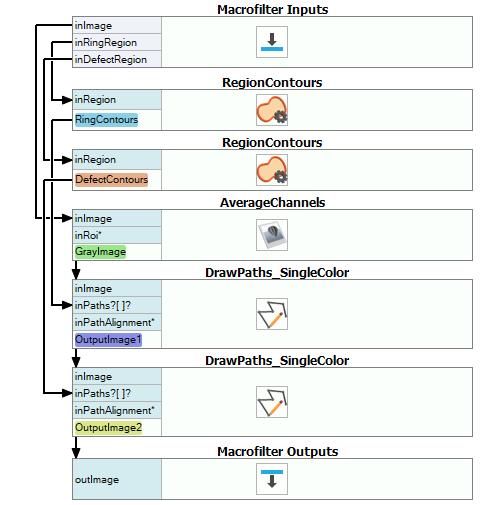
Macrofilter DrawDefects
Used Filters
| Icon | Name | Description |
|---|---|---|
| CloseRegion | Filling-in small gaps in a region without making it thicker. | |
| FillRegionHoles | Adds pixels to the input region so that it contains no holes. | |
| EnumerateImages | Emulates image acquisition with images stored on disk. | |
| DrawPaths_SingleColor | Draws paths on an image with a single color. | |
| AverageChannels | Creates a monochromatic image by averaging the input image channels. | |
| ThresholdToRegion_HSx | Extraction of a region characterized with a specific color. | |
| OpenRegion | Removing small parts from a region without making it thinner. | |
| RegionContours | Computes an array of closed paths corresponding to the contours of the input region. |
Further Readings
- Blob Analysis - Article presents detailed information about the Blob Analysis technique.