
You are here: Start » Program Examples » Hand-Eye Calibration - On Filters
Hand-Eye Calibration - On Filters
Aim
The goal of this application is to perform a complete calibration, which includes image distortion removal, perspective removal and hand-eye calibration, using filters instead of dedicated editor. This functionality is crucial when calibration performed directly from HMI is needed. A typical application of this process is Hand-Eye calibration in the production environment.
A robotics engineer should be able to select a number of appropriate Grid point coordinates and for each of them provide the Real World Points (here called Calibration points) obtained from the robot's interface. Based on this input data and image of calibration grid, the program should prepare a RectificationMap with all calibration data stored inside. Finally after clicking Exit Application the RectificationMap will be saved to disk. Additionally, after calibration, the program should compute a set of Test points, in which for each Grid point a corresponding Robot Point should be provided. The above mentioned requirements refer to the content and functionalities of the Calibration tab. The program should be implemented in Main worker task. Moreover, the HMI should also contain an Inspection tab as well as corresponding Inspection worker task, implementing a typical usage of the Rectification Map.
Input
An image of the circle calibration grid.
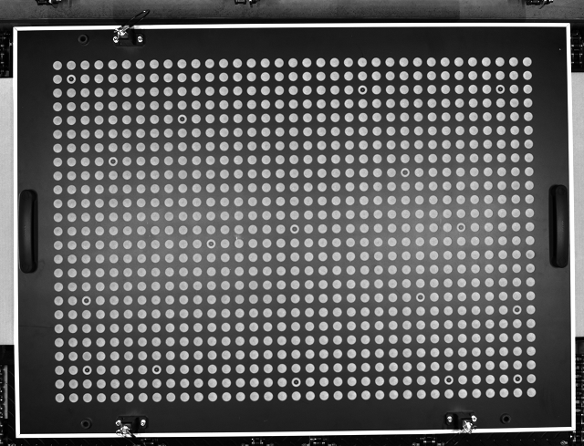
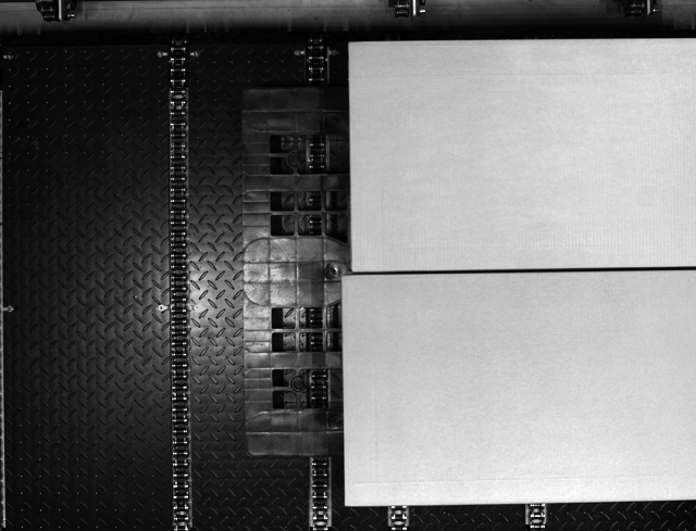
Image with objects.
Output
Rectified image with world coordinates point.
Hints
Create a RectificationMap file in the Main Worker Tasks using filters from camera calibration filters. Use this file later in the Inspection Worker Task.
Labeling connections is explained in this article.
Solution (AVS)
Load calibration image and create the HMI:
-
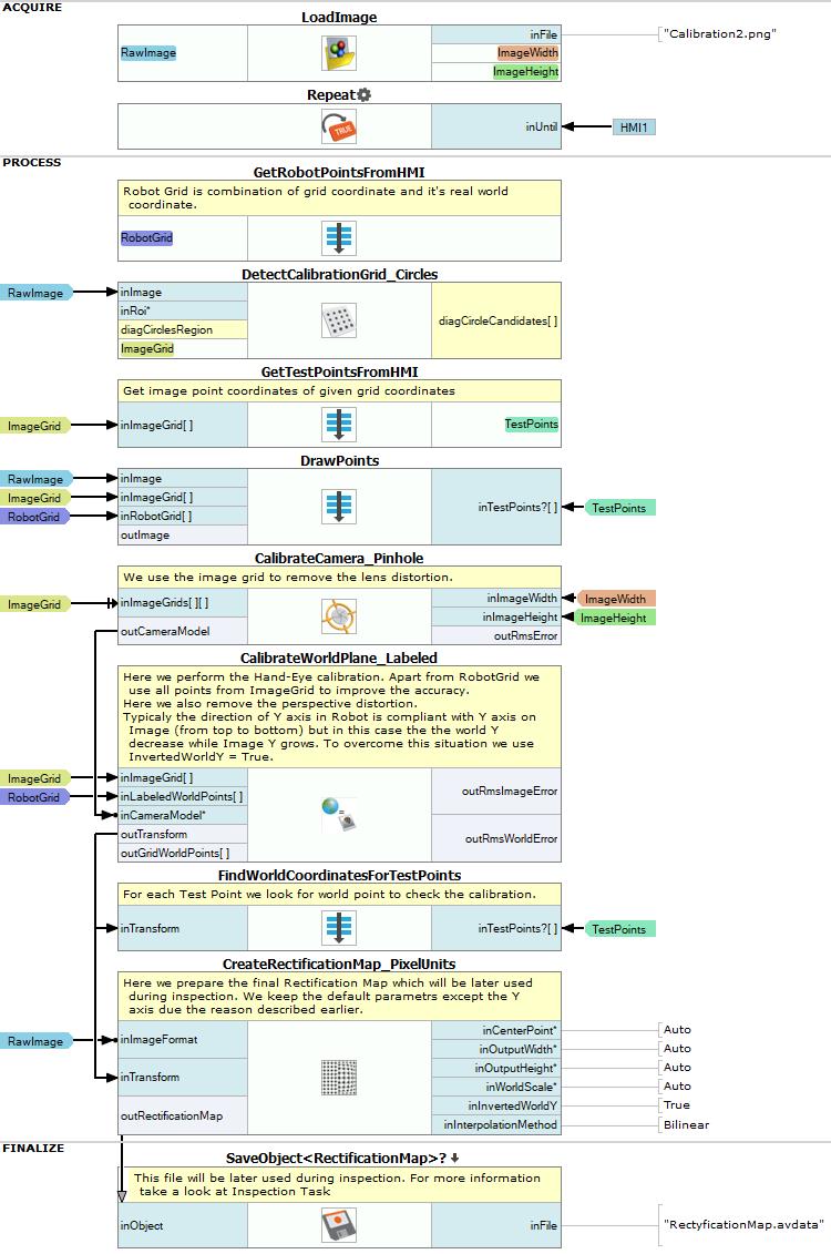
Go to the ACQUIRE section. Add a LoadImage filter and specify the images directory in inFile.
-
Add a Loop filter.
-
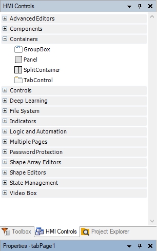
Create the HMI, which will be used in this application. Open the HMI layout designer as shown on image below. You should now be able to edit the content and layout of the HMI window.

-
Open the "Containers" category, next drag and drop the TabControl control into the HMI designer. Resize this control to the size of the HMI panel. Change tabs description in the Properties window and change tab names from "tabPage1" and "tabPage2" to "Calibration" and "Inspection".
-
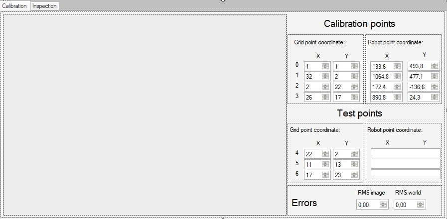
In TabControl switch to the "Calibration" tab. Drag and drop View2DBox control from the "Indicators" category into the HMI window. Resize its size to suit the design of your HMI and change the InitialSizeMode from OriginalSize to FitToWindow in the Properties window.
-
Basing on the image above, create sections next to View2DBox control. To create sections use Panel controls from "Container" category.
-
Create boxes for numerical values using NumericUpDown controls from "Controls" category as shown in the image above. In case of "Robot point coordinate" and "Errors" sections use Properties window to set DecimalPlaces to 1, Maximum to 5000 and Minimum to -5000.
-
In the second "Test points" section ("Robot point coordinate") insert TextBox controls from the "Controls" category.
-
Label data as shown in the image above with Label controls from "Controls" category.
-
Assign the following annotations to the NumericUpDown controls in the first "Calibration points" section ("Grid point coordinate"):
-
X:1 Y:1
-
X:32 Y:2
-
X:2 Y:22
-
X:26 Y:17
-
-
Assign the following Real World values to the NumericUpDown controls in the second "Calibration points" section ("Robot point coordinate"):
-
X:133,6 Y:493,8
-
X:1064,8 Y:477,1
-
X:172,4 Y:-136,6
-
X:890,8 Y:24,3
-
-
Assign the following annotations to the NumericUpDown controls in the first "Test points" section ("Grid point coordinate"):
-
X:22 Y:2
-
X:11 Y:13
-
X:17 Y:23
-
-
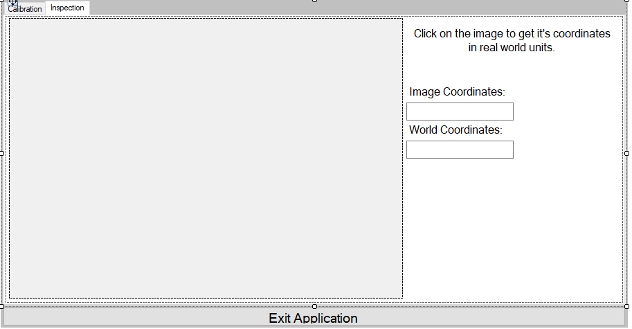
Go to the "Inspection" tab in the TabControl. Drag and drop View2DBox control from the "Indicators" category and resize this control to suit your preference. Next, change InitialSizeMode from OriginalSize to FitToWindow in the Properties window.
-
Use TextBox controls from "Controls" category to create boxes for calculated values as shown in the image above.
-
Label data, as shown in the image above, using Label controls from "Controls" category.
-
Add an Impulse Button from "Controls" category below the TabControl. Change default text to Exit Application in the Properties window.
Now that the HMI for setting Real World Points is ready, we can proceed to creating Main program for the calibration.
-
Go to the PROCESS section, next add Step Macrofilter to the main program and name it "GetRobotPointsFromHMI".
-
Add a Formula inside the previously created macrofilter.
-
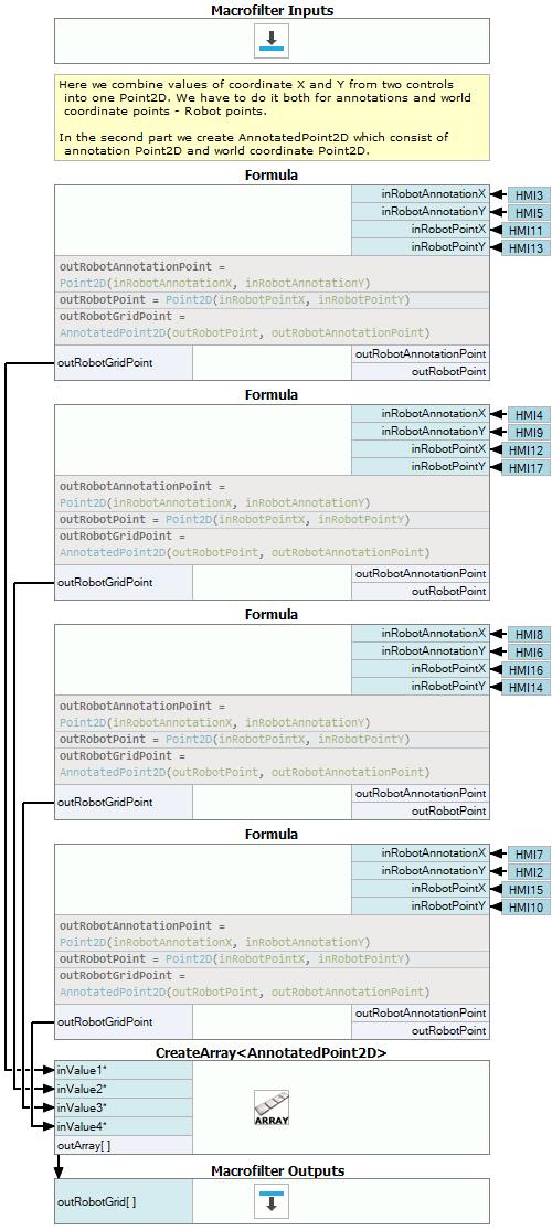
Drag and drop NumericUpDown control's outValue output to the Formula and create Real type inputs. Formula inputs should be named as shown on image below. Create connections between HMI and the Formula inputs so that:
- outValue of grid point coordinate X is connected with inRobotAnnotationX Formula's input,
- outValue of grid point coordinate Y is connected with inRobotAnnotationY Formula's input,
- outValue of robot point coordinate X is connected with inRobotPointX Formula's input,
- outValue of robot point coordinate Y is connected with inRobotPointY Formula's input.
-
Use the code from image above to create Formula's outputs. Copy created Formula three times and connect each grid point coordinate and robot point coordinate from HMI with the Formula.
-
Add CreateArray filter and connect outRobotGridPoint output from each Formula with the inValue of CreateArray filter.
-
Create a macrofilter output with AnnotatedPoint2DArray type and name it outRobotGrid. Connect outArray output of CreateArray filter with the created output.
-
Go back to Main. Add DetectCalibrationGrid_Circles filter.
-
Connect outImage output from LoadImage filter with the inImage input of DetectCalibrationGrid_Circles. Set inCircleRadius to 15.
-
Make a new AnnotatedPoint2DArray type input in the created macrofilter and name it inImageGrid.
-
Connect outImageGrid output from DetectCalibrationGrid_Circles filter with the newly created macrofilter input.
-
Go to the "GetTestPointsFromHMI" macrofilter and create a new Formula inside.
-
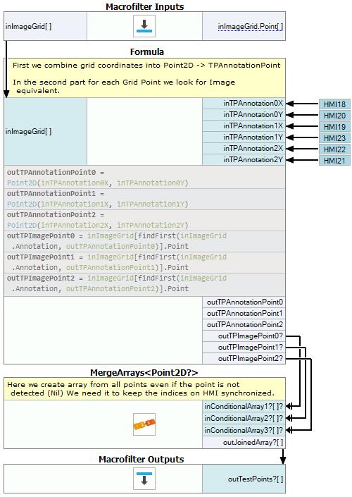
Create an AnnotatedPoint2DArray Formula's input, name it inImageGrid and connect it with the macrofilter's input. In this step grid coordinates are combined into test annotation points with Point2D data type and then for each Grid Point its Image equivalent is being located.
-
Create 6 Real type Formula inputs and name them as shown in the above image.
-
Connect Grid point coordinate (test points) from HMI to the Formula so that:
- point's 4 outValue of Grid point coordinate X is connected with inTPAnnotation0X Formula's input,
- point's 4 outValue of Grid point coordinate Y is connected with inTPAnnotation0Y Formula's input,
- point's 5 outValue of Grid point coordinate X is connected with inTPAnnotation1X Formula's input,
- point's 5 outValue of Grid point coordinate Y is connected with inTPAnnotation1X Formula's input,
- point's 6 outValue of Grid point coordinate X is connected with inTPAnnotation2X Formula's input,
- point's 6 outValue of Grid point coordinate Y is connected with inTPAnnotation2X Formula's input.
-
Use the code from image above to create Formula outputs. outTPAnnotationPoint outputs should have Point2D data type and outTPImagePoint outputs should have Point2D? data type assigned to them.
-
Add a MergeArrays filter to the current macrofilter and connect Formula's outTPImagePoint outputs with its inputs. This step allows to keep the indices on HMI synchronized.
-
Create a macrofilter output with Point2D?Array data type and name it outTestPoints. Connect outJoinedArray output from MergeArrays filter with the created macrofilter output.
-
Go back to Main. Add a Step Macrofilter and name it "DrawPoints".
-
Add following inputs to the created macrofilter:
- inImage input with Image data type,
- inImageGrid input with AnnotatedPoint2DArray data type,
- inRobotGrid input with AnnotatedPoint2DArray data type,
- inTestPoints input with Point2D?Array data type.
-
Connect created inputs with following this scheme:
- Connect outImage output from LoadImage filter with the inImage input of "DrawPoints" macrofilter,
- Connect outImageGrid output from DetectCalibrationGrid_Circles filter with the inImageGrid input of "DrawPoints" macrofilter,
- Connect outRobotGrid output from "GetRobotPointsFromHMI" macrofilter with the inRobotGrid input of "DrawPoints" macrofilter,
- Connect outTestPoints output from "GetTestPointsFromHMI" macrofilter with the inTestPoints input of "DrawPoints" macrofilter.
-
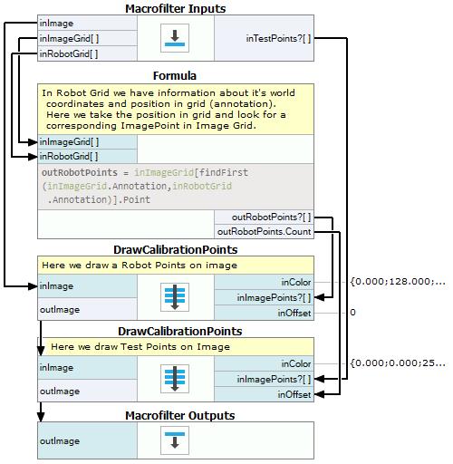
Go to "DrawPoints" macrofilter and create a new Formula inside.
-
Create AnnotatedPoint2DArray Formula's input, name it inImageGrid and connect it with the macrofilter's inImageGrid input.
-
Create AnnotatedPoint2DArray Formula's input, name it inRobotGrid and connect it with the macrofilter's inRobotGrid input.
-
Use the code from image above to create Formula's outputs. outRobotPoints output should have Point2D?Array data type assigned to it.
-
Click on the Show/hide Ports > outRobotPoints > Count to display Formula's outRobotPoints.Count output.
-
Add a Step Macrofilter and name it "DrawCalibrationPoints".
-
Add following inputs to the created macrofilter:
-
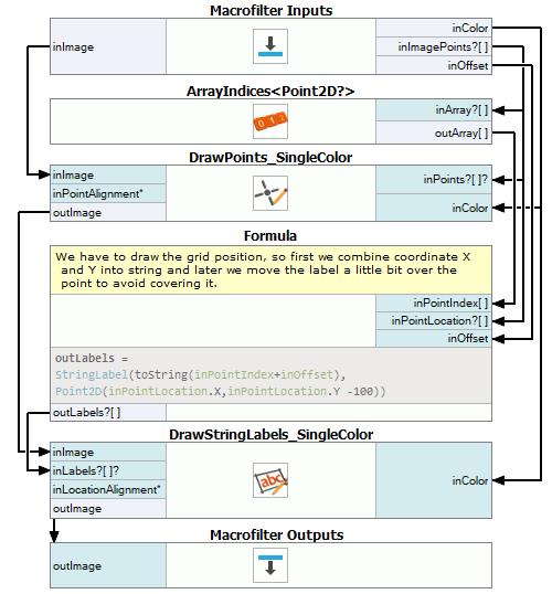
Go to the "DrawCalibrationPoints" macrofilter.
-
Add an ArrayIndices filter, connect macrofilter's inImagePoints input with the inArray input.
-
Add a DrawPoints_SingleColor filter, connect its inputs using the following scheme:
- Connect macrofilter's inImage input with the inImage input of DrawPoints_SingleColor filter,
- Connect macrofilter's inImagePoints input with the inPoints input of DrawPoints_SingleColor filter,
- Connect macrofilter's inOffset input with the inColor input of DrawPoints_SingleColor filter.
-
Add a Formula block and create its inputs using following scheme:
- inPointIndex input with IntegerArray data type,
- inPointLocation input with Point2D?Array data type,
- inOffset input with Integer data type.
-
Connect created inputs using following scheme:
- Connect outArray output from ArrayIndices filter with the "inPointIndex" Formula input,
- Connect inImagePoints macrofilter's input with the "inPointLocation" Formula input,
- Connect inOffset macrofilter's input with the "inOffset" Formula input.
-
Use the code from the image above to create a Formula's output. Labels output should have StringLabel?Array data type assigned to it.
-
Add a DrawStringLabels_SingleColor filter and create connections using following scheme:
- Connect outImage output from DrawPoints_SingleColor filter with the inImage input of DrawStringLabels_SingleColor filter,
- Connect formula's outLabels output with the inLabels input of DrawStringLabels_SingleColor filter,
- Connect macrofilter's inColor input with the inColor input of DrawStringLabels_SingleColor filter.
-
Create a Image data type macrofilter output and name it outImage, connect outImage with that output.
-
Go to the "DrawPoints" macrofilter. Copy the "DrawCalibrationPoints" macrofilter to have 2 of them inside the "DrawPoints" macrofilter.
-
Make connections for the first "DrawCalibrationPoints" macrofilter using following scheme:
- Connect "DrawPoints" macrofilter's inImage input with the inImage input of "DrawCalibrationPoints" macrofilter,
- Set inColor input to {0,000;128,000;0,000;0,000},
- Connect Formula's outRobotPoints output with the inImagePoints input,
- Set inOffset to 0.
-
Make connections for the second "DrawCalibrationPoints" macrofilter using following scheme:
- Connect (first) "DrawCalibrationPoints" macrofilter's outImage output with the inImage input of "DrawCalibrationPoints" macrofilter,
- Set inColor input to {0,000;0,000;255,000;0,000},
- Connect "DrawPoints" macrofilter's inTestPoints input with the inImagePoints input of "DrawCalibrationPoints" macrofilter,
- Connect Formula's outRobotPoints.Count output with the inOffset input,
- Connect (second) "DrawCalibrationPoints" macrofilter's outImage output with the inImage input of View2DBox control in the "Calibration" tab.
-
Create a Image data type "DrawPoints" macrofilter output and name it outImage. Connect outImage output of the (second) "DrawCalibrationPoints" macrofilter with this created output.
-
Go to the Main macrofilter and add a CalibrateCamera_Pinhole filter.
-
Make connections with the added filter:
- Connect outImageGrid output from DetectCalibrationGrid_Circles filter with the inImageGrids input of CalibrateCamera_Pinhole filter,
- Connect outImage.Width output from LoadImage filter with the inImageWidth input of CalibrateCamera_Pinhole filter,
- Connect outImage.Height output from LoadImage filter with the inImageHeight input of CalibrateCamera_Pinhole filter,
- Set inDistortionType to Polynomial.
-
Add a CalibrateWorldPlane_Labeled filter.
-
Make connections with the added filter:
- Connect outImageGrid output from DetectCalibrationGrid_Circles filter with the inImageGrid input of CalibrateWorldPlane_Labeled filter,
- Connect outRobotGrid output from "GetRobotPointsFromHMI" macrofilter with with the inLabeledWorldPoints input of CalibrateWorldPlane_Labeled filter,
- Connect outCameraModel output from CalibrateCamera_Pinhole filter with with the inCameraModel input of CalibrateWorldPlane_Labeled filter,
- Set inInvertedWorldY to True,
- Connect outRmsImageError output from CalibrateWorldPlane_Labeled filter with the first NumericUpDown control labeled as "RMS image",
- Connect outRmsWorldError output from CalibrateWorldPlane_Labeled filter with the second NumericUpDown control labeled as "RMS world".
Hand-Eye Calibration is now ready. Run the program and test the created calibration while also checking for RMS Errors. Create a rectification map and save it in order to use it in the Inspection task.
-
Go to the PROCESS section in Main macrofilter and add a new "Step Macrofilter", name it "FindWorldCoordinatesForTestPoints".
-
Add following inputs to the created macrofilter:
- inTransform input with RectificationTransform data type,
- inTestPoints input with Point2D?Array data type.
-
Connect created inputs using following scheme:
- Connect outTransform from CalibrateWorldPlane_Labeled filter with the inTransform input of "FindWorldCoordinatesForTestPoints" macrofilter,
- Connect outTestPoints output from "GetTestPointsFromHMI" macrofilter with theinTestPoints input of "FindWorldCoordinatesForTestPoints" macrofilter.
-
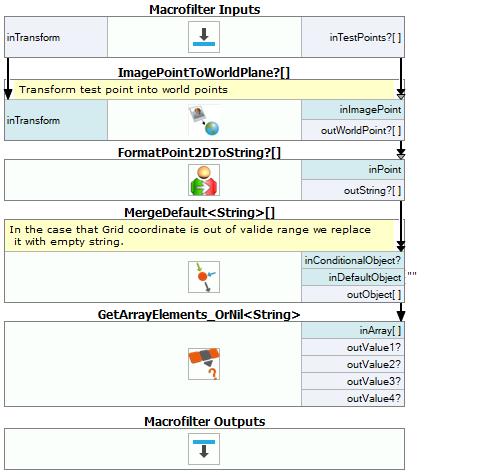
Go to the "FindWorldCoordinatesForTestPoints" macrofilter.
-
Add a ImagePointToWorldPlane filter and connect its inputs using following scheme:
- Connect inTestPoints macrofilter input with the inImagePoint input of ImagePointsToWorldPlane filter.
- Connect inTransform macrofilter input connect with the inTransform input of ImagePointsToWorldPlane filter.
-
Add a FormatPoint2DToString filter and connect its inPoint input with the outWorldPoints output of ImagePointsToWorldPlane filter.
-
Add a MergeDefault filter with String data type variant.
-
Connect outString output from FormatPoint2DToString filter with the inConditionalObject input of MergeDefault filter.
-
Add a GetArrayElements_OrNil filter and connect its inArray input with the outObject output of MergeDefault filter.
-
Connect outValues from GetArrayElements_OrNil to the corresponding TextBox controls placed in the HMI "Test Points" section, which are labeled as "Robot point coordinates".
-
Go to the Main macrofilter and add a CreateRectificationMap_PixelUnits filter.
-
Make connections with the added filter:
- Connect outImage output from LoadImage filter with the inImageFormat input of CreateRectificationMap_PixelUnits filter,
- Connect outImage output from LoadImage filter with the inImageFormat input of CreateRectificationMap_PixelUnits filter,
- Set inIInvertedWorldY to True.
-
Add an Exit filter and connect its inCondition input with the outValue of the ImpulseButton in the HMI, labeled as "Exit Application".
-
Go to the FINALIZE section. Add a SaveObject filter and connect its inObject input with the outRectificationMap output of CreateRectificationMap_PixelUnits filter.
-
Set inFile to RectificationMap.avdata.
Hand-Eye Calibration is ready and it was tested. Now it can be used in inspection:
-
Create new Worker Task from the Project Explorer window and name it as "Inspection".
-
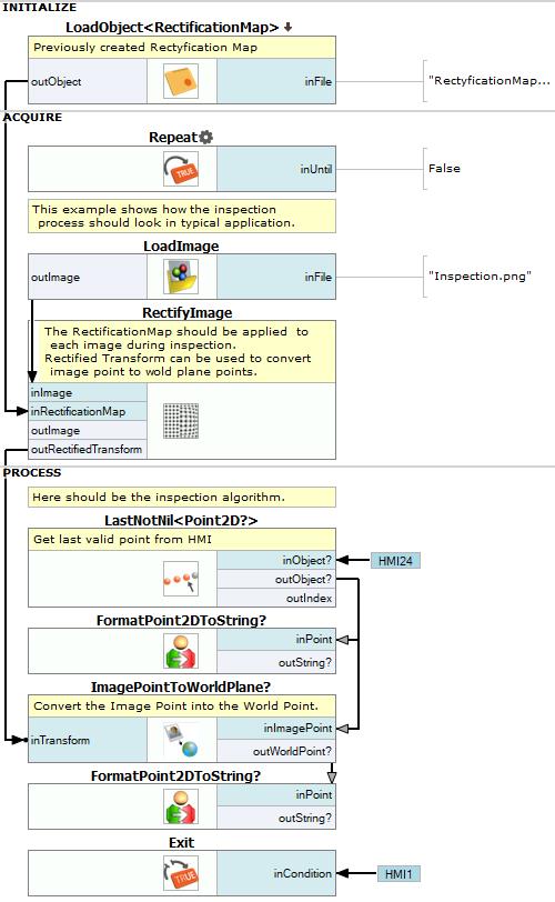
Go to the the INITIALIZE section in the new created Worker Task macrofilter.
-
Add a LoadObject filter with the RectificationMap data type variant. Set inFile to the RectificationMap.avdata.
-
Go to the ACQUIRE section and add a Loop filter.
-
Add a LoadImage filter and set inFile to the Inspection.png.
-
Add a RectifyImage filter and create connections with it:
- Connect outObject output from LoadObject filter with the inRectificationMap input of RectifyImage filter,
- Connect outImage output from LoadImage filter with the inImage input of RectifyImage filter,
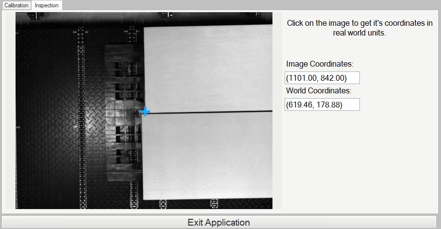
- Connect outImage with inImage input of View2DBox indicator in the "Inspection" tab.
-
Go to the PROCESS section and add a LastNotNil filter with Point2D? data type.
-
Right click on the View2DBox indicator in the "Inspection" tab, then click on the Edit Ports and Events Visibility and check in outLeftClick. Connect created output from the View2DBox to inObjects input of LastNotNil filter.
-
Connect outObject output from the LastNotNil filter with the inData1 input of the View2DBox indicator.
-
Add a FormatPoint2DToString filter and connect its inPoint input with the outObject output of the LastNotNil filter.
-
Connect outString output from FormatPoint2DToString filter with the TextBox control labeled as "Image Coordinates:".
-
Add a ImagePointsToWorldPlane filter and connect its inputs using following scheme:
- Connect outRectifiedTransform output from RectifyImage filter with the inTransform input of ImagePointToWorldPlane filter,
- Connect outObject output from LastNotNil filter with the inImagePoints input of ImagePointsToWorldPlane filter.
-
Add a FormatPoint2DToString filter and connect its inPoint input with the outWorldPoints output of ImagePointsToWorldPlane filter.
-
Connect outString output from FormatPoint2DToString with the inText input of TextBox control labeled as "World Coordinates".
-
Add an Exit filter and connect its inCondition input with the outValue output of ImpulseButton labeled as "Exit Application".
Hand-Eye Calibration and inspection are now ready to use. Test the created program.
Macrofilter Main
Used Filters
| Icon | Name | Description |
|---|---|---|
| LoadImage | Loads a single image from a file. | |
| ArrayIndices | Creates an array of element indices, i.e. {0, 1, 2, ..., N-1}, where N is the length of the input array. | |
| RectifyImage | Image undistortion, perspective removal. | |
| SaveObject | Saves an object to a file. | |
| DrawPoints_SingleColor | Draws points on an image with a single color. | |
| GetArrayElements_OrNil | Extracts up to 8 individual elements from an array or NIL for indices out of range. | |
| MergeArrays | Concatenates conditional arrays one after another. Any array that is Nil becomes skipped. | |
| CalibrateWorldPlane_Labeled | Image to world coordinates transformations. | |
| MergeDefault | Usually used to create a definite result for the special cases represented by the Nil value. | |
| DrawStringLabels_SingleColor | Draws strings (text) on an image with a single color. | |
| DetectCalibrationGrid_Circles | Camera calibration, image to world coordinates transformations. | |
| LoadObject | Loads an object from a file. | |
| Exit | If the specified condition is true, exits the macrofilter loop. | |
| CreateRectificationMap_PixelUnits | Image undistortion, perspective removal. | |
| CreateArray | Creates an array from up to 8 individual objects. | |
| Repeat | Put this filter into a task that should have a loop, but does not have any other loop generators (e.g. GrabImage). | |
| FormatPoint2DToString | Converts a 2D point to a string of format "(X, Y)". | |
| ImagePointToWorldPlane | Undistortion, image to world coordinate transformation. | |
| LastNotNil | Returns the last value passed that existed. | |
| CalibrateCamera_Pinhole | Camera calibration, image to world coordinates transformations. |
Further Readings
- Camera Calibration and World Coordinates - Detailed information about camera calibration and world coordinates.