
You are here: Start » Machine Vision Guide » Camera Calibration
Camera Calibration
Introduction
Camera calibration is a process of creating an image deformation model, which can be used to recover an undeformed image. Adaptive Vision Studio makes it possible to model lens distortions as well as perspective, cylindrical and spherical transformations. It is often required both in 2D and 3D applications. In the case of 2D vision it is necessary for performing reliable measurements.
 |
 |
Removing lens distortion using camera calibration filters. Images before and after remapping.
Type SpatialMap
Computation of the deformation model is a very complex process and can take significant time. To assure the highest performance this process is performed once and the model is stored in the SpatialMap type.
The type SpatialMap is a map of image locations and their corresponding positions after removal of distortion. The process of transforming an input image to an image without distortion is called remapping. It is very fast, because it only translates pixels by precomputed vectors.
Deformation Types
The purpose of remapping of an image is to recover the image from before deformation. Some deformations result from physical imperfection of the used optics, other are caused by the physical shape of the object under inspection. Adaptive Vision Studio provides tools for dealing with several different deformation types.
Lens Distortion
This unwanted distortions are introduced by imperfections of camera lenses. It is common for low-cost wide-angle lenses to introduce radial (barrel) distortion. The effect is that straight lines in reality are not reproduced as such in the recorded image. The central area in the image usually has little distortion, and the effect becomes stronger toward the borders of the image.
Note: The lens imperfections also introduce the vignette effect which results in darkening of the image pixels with the distance to the center of the lens. This kind of deformations is not covered in this document, but it can be fixed using basic image processing filters.
The manual process of computing a lens distortion model consists of the following steps:
-
Gathering images – the most important step is to gather images that will be used
to determine lens intrinsic parameters. Two most common methods can be used:
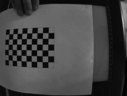
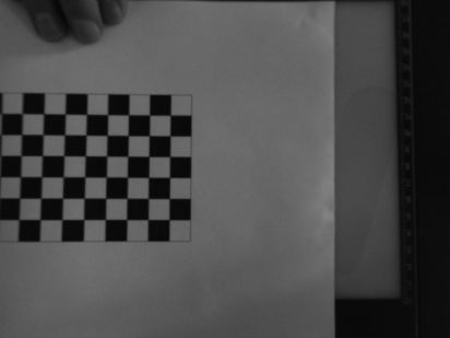
- Calibration using chessboards – this method requires to use a special calibration grid that can be bought or printed. Quality of the calibration depends on the calibration grid. The filter DetectChessboardGrid is prepared to extract points from such grids.
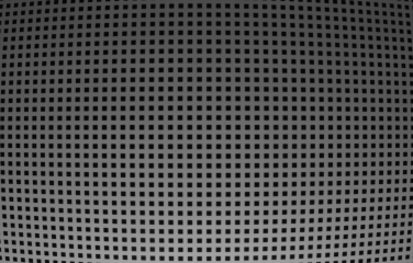
- Calibration using custom grids – to calibrate camera the calibration grid is needed. Filter AnnotateGridPoints computes a difference in the position of the grid points between real images and the computed calibration grid.
- Finding camera parameters – calculating camera distortion coefficients (camera matrix) using the found 3D object points and theirs projections in the 2D space. To find a camera matrix the CalibrateCamera filter can be used.
- Preparing a spatial map – the CreateUndistortionMap filter uses the camera matrix to compute a spatial map. The result can be saved to a file for later use.
- Remapping an image – use filter the UndistortImage filter to remove distortions from an input image.
 |
 |
Remapping an image with a custom dot-based calibration grid.
Perspective Removal
In some cases the camera is located at a position in which the objects can be deformed due to perspective transform.
To remove perspective distortion the filter CreatePerspectiveMap_Path can be used. This filter requires a path made of four points. The first point should indicate the top-left corner of the object. Next corner points should be marked in clockwise order: top-right, bottom-right and bottom-left.
 |
 |
The left image shows a tilted QR code. The perspective is removed in the right image.
Geometric Deformation
This kind of distortions are introduced by the shape of the physical object on the image. Calculation of a distortion model for these object is necessary to perform image analysis.
There are several filters for creating spatial maps for an object with a geometric distortion:
- Cylinder (CreateCylinderMap) – e.g. flattening of a bottle label.
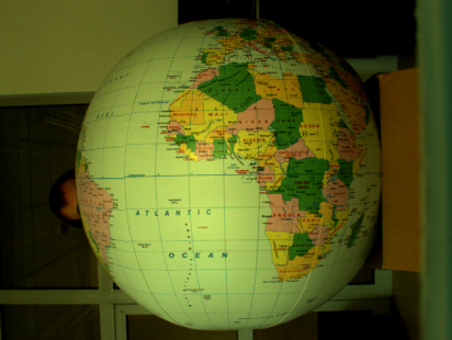
- Sphere (CreateSphereMap) – e.g. reading a label from light bulb.
- Circular objects (polar transform) (CreateImagePolarTransformMap) - e.g. reading a label wrapped around a DVD disk center.
 |
 |
Example of remapping of a spherical object using CreateCylinderMap and RemapImage. Image before and after remapping.
Other Transforms (Warping)
Image remapping can also be used to perform other geometric transforms, especially affine image transforms. If the transform parameters are fixed (e.g. the rotation angle), then this approach results in higher performance than can be achieved with regular filters (e.g. RotateImage). Examples of such operations are: CreateImageRotationMap, CreateImageResizeMap or CreateMatrixTransformMap.
Furthermore custom spatial maps can be created with ConvertMatrixMapsToSpatialMap.
 |
 |
An example of custom image transform created with ConvertMatrixMapsToSpatialMap. Image before and after remapping.