You are here: Start » Tutorial Exercises » Removing Camera Lens Distortion: Square pattern (distortions2)
Removing Camera Lens Distortion: Square pattern (distortions2)
Aim
This exercise shows how to calibrate a camera in order to remove lens distortion from an image using a non standard calibration pattern.
Input
A single input file with lens distortions. The input image contains calibration pattern made of squares. Part of the pattern is visible only partially.
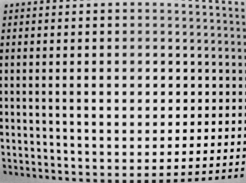
The input image is stored in
distortion2directory.
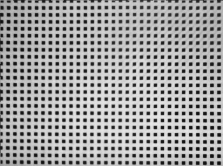
Output
An image after remapping using created spatial map.
Hints
This example presents a way to calibrate a camera using a non-standard calibration pattern. This example consists of two steps. the first step is to extract points from the image. The second is to perform the calibration of the camera.
Some of image's squares are cut, so to get the best results it is necessary to select only fully visible squares.
The best way to extract squares from a background image is to use ThresholdToRegion_Dynamic filter because this algorithm is invulnerable to background changes.
To get stable positions of Region centers use RegionMassCenter.
The process of calibration of the camera needs actual image size. To get Image dimensions expand needed structure fields on an output of LoadImage filter.
Remember, that calibration has to be repeated if any of the following changes:
- Camera lens is replaced with other (different lens distortions).
- Different image resolution is selected (scale change, camera matrix is different).
- The camera position relative to the observed plane changes.
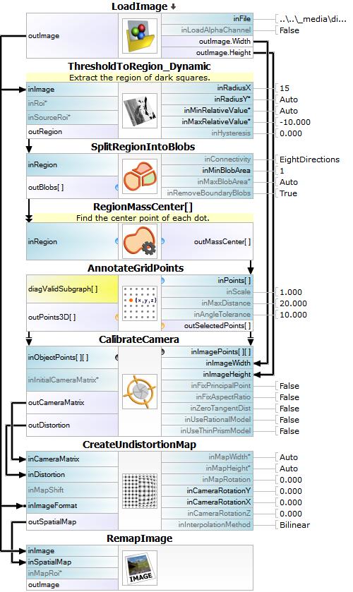
Solution (AVS)
-
Create a new project and add LoadImage. Enter image path.
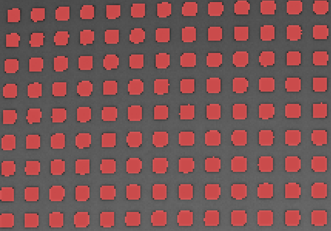
-
Next step is to extract the calibration squares from the background. For this purpose use ThresholdToRegion_Dynamic filter. Add it to the program and set inRadiusX to 15. Set inMaxRelativeValue to -10,0. The image below shows squares' regions obtained after thresholding.
-
Split elements using SplitRegionIntoBlobs. In this step partially visible dots can be removed. To do that set inRemoveBoundaryBlobs to True.
-
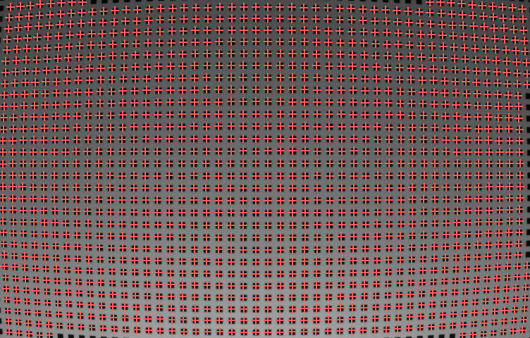
To calculate the center point of each region add RegionMassCenter filter. The image below shows calculated mass centers.
-
To calculate world points add AnnotateGridPoints filter and set inMaxDistance to 20.0. This filter selects points that lay on calculated grid. It also calculates positions of points in world coordinates.
-
To calibrate camera use CalibrateCamera filter with dimensions of the actual image obtained from expanded outputs of LoadImage filter.
-
To create a SpatialMap use CreateUndistortionMap filter and to remap the input image use RemapImage filter. Image below show points before remapping (red) and after (green).
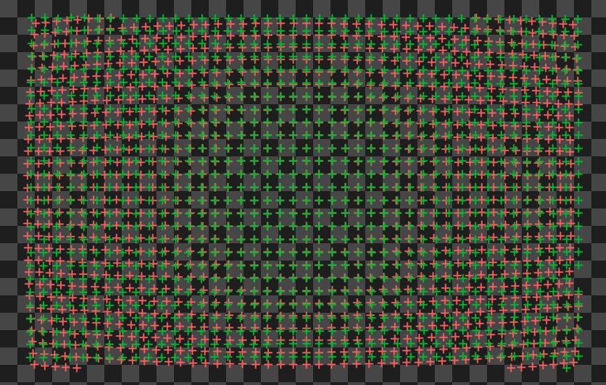
Main Macrofilter performs calibration of the camera and remapping of the input image.