
You are here: Start » Program Examples » Photometric Stereo Braille
Photometric Stereo Braille
Aim:
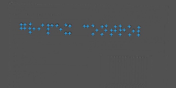
The task is to create an algorithm that will extract the dots of the Braille Code from a box.
Input:
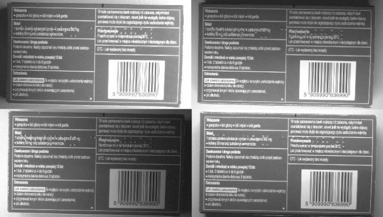
Four images taken with different directions of illumination.
Output:
Hints:
-
Illumination should change clockwise and in a predefined order.
-
Labeling connections is explained in this article.
Solution (Studio)
-
Load four images of the same object and put them in the order they are illuminated:
- right
- bottom
- left
- top
-
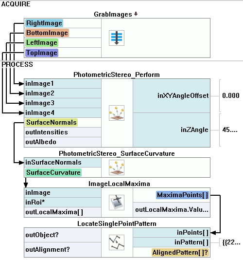
Select all LoadImage filters, right-click on them, and choose Extract Step Macrofilter to create a Step Macrofilter. Name it GrabImages and create four outputs in the same order as before. You can name the outputs right, bottom, left and top to avoid confusion.
-
Connect corresponding outputs from the macrofilter to the PhotometricStereo_Perform filter.
-
The inXYAngleOffset describes the direction of light that is projected into the XY plane by a first light source. 0 means that the light comes from the right, while the offset of 90 means that the light comes from the bottom. In this example, the first image shows the box illuminated from the right, so a change of the default value is not needed.
-
The inZAngle describes the angle between the optical axis of the camera (Z-axis) and the direction of the illumination. In this example, the object was illuminated at an angle of 45 degrees.
-
Add the PhotometricStereo_SurfaceCurvature to compute the surface curvature required to get information about the Braille code. Connect the outSurfaceNormals of the PhotometricStereo_Perform filter with the inSurfaceNormals input.
-
Set the inSmoothingStdDevX to 4, the inOffset to 40, and the inScale to 100000. That high value is needed for visualization purposes. You may change the parameters to learn how they influence the output. Drop the outSurfaceCurvature to the preview to see the results.
-
To find the dots of the Braille code, use the ImageLocalMaxima filter. Its outLocalMaxima.Point output can be used, e.g., for verifying whether the code is correct.
-
To confirm that the detected code is correct, you can use the LocateSinglePointPattern filter. Add it at the end of your program and connect the outLocalMaxima.Point to the inPoints.
-
Now you need to specify a point pattern. To do so, click the inPattern in the Properties window and mark all the dots that should be detected by the algorithm. To make your work easier, you can iterate the program once beforehand and use a reference image in the editor as a background for that process.
-
Set the MaxAngle to 20, MinAngle to -20, and show the outAlignedPattern on the data preview to compare it with the detected points.
Macrofilter Main
Used Filters
| Icon | Name | Description |
|---|---|---|
| ImageLocalMaxima | Detection of characteristic points, usually after some image transformations. | |
| LoadImage | Loads a single image from a file. | |
| LocateSinglePointPattern | Can be used to find an entire object after finding its characteristic points with tools such as Template Matching or DL_LocatePoints. | |
| PhotometricStereo_Perform | Computes surface normals using four images with light source in different places. | |
| PhotometricStereo_SurfaceCurvature | Computes the surface curvature using previously computed normals. |
Further Readings
- Image Processing - A comprehensive introduction to Image Processing.