
You are here: Start » Program Examples » Bottle Inspection
Bottle Inspection
Aim:
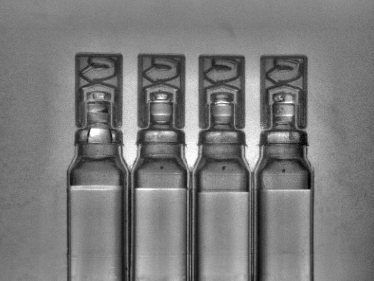
The task of this example is to check the number of bottles, their orientation, the level of a liquid and the presence of foam.
Input:
An image of bottles. The position of the bottles may change both in relation to the camera as and other bottles.
Output:
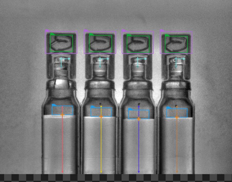
An image with the result of the inspections drawn on it. If a defect is detected, a rectangle is drawn around it.
The Webhmi and the HMI attached to the solution:


Hints:
The location of the object is variable. Some of the steps for this program are described in the following tutorials:
Bottle Inspector Part 1: Counting Bottles
Bottle Inspector Part 2: Measuring Liquid Level
Bottle Inspector Part 3: Foam Detection
The orientation of the bottle can be determined by finding an asymmetrical part of the bottle, like the top of it.
In the following articles, you can find information about designing WebHmi and the Event Handling mechanism:
Solution (AVS):
-
In Workspace Explorer, open the workspace Examples, and in the Filmstrip window select BottleInspection dataset. Drag the Image channel to the ACQUIRE section.
-
Follow the steps described in the tutorials mentioned in the Hints section.
-
When the program resembles the one from the end of the third tutorial, add the AlignRectangle filter.
- Connect the outBottleAlignments output form the CreateCoordinateSystemFromPoint to the inAlignment input.
- Iterate the program once. Enter the editor (click "..." next to the inRectangle) and draw a rectangle approximately the size of the cap of a bottle.
- Drag the outAlignedRectangle to one of the inData ports of the view2DBox_PassFail indicator in the HMI.
- Make sure the Coordinate System field is set to inAlignment and then move the rectangle onto the cap.
- Iterate the program once and click on the "..." icon next to the inRectangle. In the editor, draw a small rectangle (about 15x15 pixels should be enough) roughly in the center of the cap.
- Make sure you put the rectangle on the same bottle where the coordinate system is.
- The result should look like the image below. Notice how the coordinate system symbol is below the rectangle.

-
Add the LocateSingleObject_Edges1 filter. Connect the inSearchRegion input with the outAlignedRectangle output.
- Open the edge model editor. Mark the area shown in the provided image. Use the settings from the image as well.

- After closing the editor, change the filter properties. Set the inEdgeThreshold to 8 and the inMinScore to 0.5.
- The inEdgeThreshold parameter determines how strong the transition between pixels must be to be considered an edge. The inMinScore parameter determines the minimum score of a valid object occurrence. In this case, we are only interested in finding the orientation of the cap, so the minimum score must be relatively low.
- By clicking on Show/Hide Ports, you can show additional outputs and inputs. Check the option as shown in the following image, so that the filter has another output: outObject.isNil.Not.
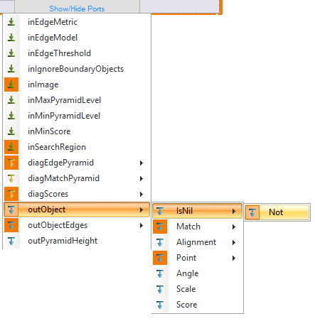
- Connect the newly created output to the the inStatus port of the view2DBox_PassFail HMI indicator. That port should correspond to the previously used inData port (step 2).
- Now, if the object is detected (orientation is correct) the created output is True and the rectangle from the previous step is green. When no object is detect (orientation is wrong), the rectangle is red.
- Open the edge model editor. Mark the area shown in the provided image. Use the settings from the image as well.
-
To organize the program a bit more, you can extract filters into step macrofilters.
-
To add a WebHMI subsystem, choose Edit » Add Web HMI... and select a WebHMI template that fits the target layout. The template is just a starting point that can be freely modified. Titled Picture with controls were used:

-
Arrange the WebHmi controls using StackPanel controls.
-
To add controls to StackPanel, click
 action button and choose Add Content... option.
 -
Add and connect StatusIndicator controls.
-
Add TextBlock controls to title StatusIndicators.
-
Connect inputs and outputs of the created program with the WebHmi controls.
Macrofilter Main

Macrofilter UpdateWebHmi

Used Filters
| Icon | Name | Description |
|---|---|---|
| AlignRectangle | Required when there is a rectangle defined in a local coordinate system, but the next image-related filter in the program does not have any inAlignment input. | |
| CheckPresence_Intensity | Quick and easy presence verification, e.g. for missing caps, screws, labels. | |
| CopyObject | Use this filter to create a source of data, e.g. that needs to be send to HMI or used in several places of a macrofilter. | |
| CreateCoordinateSystemFromPoint | Most often used to define an object alignment from results of 1D Edge Detection or Blob Analysis. | |
| CreateRectangle | Creates a rectangle from an aligned point. | |
| Delay | Suspends the program workflow for inTime milliseconds. | |
| DrawRectangles_MultiColor | Draws rectangles on an image with multiple colors. | |
| GetArrayElements_OrNil | Extracts up to 8 individual elements from an array or NIL for indices out of range. | |
| IntegerToString | Converts an integer to a string. | |
| LocateSingleObject_Edges1 | Detection of an object whose outlines are sharp and rigid. Often one of the first filters in a program. | |
| ScanMultipleStripes | Very fast detection of multiple pairs of opposite edges - usually for counting or width measurements. | |
| ScanSingleEdge | Very fast detection of an object (e.g. horizontal displacement of a bottle) and simple measurements (e.g. liquid level in a bottle). | |
| TestIntegerEqualTo | Checks whether two integers are equal. |
Further Readings
- 1D Edge Detection - The article explaining how edge detection filters work.
- Local Coordinate Systems - This article describes basic concept of using the coordinate systems.
- Template Matching - Most detailed description of the Template Matching technique.