
You are here: Start » Tutorial Exercises » Measure Objects
Measure Objects
Aim:
Devise an algorithm that measures the width of an object depicted in the provided images.
The measured width should be presented in a human-readable format and depicted on an input image.
Assume that the camera is calibrated and the pixels-to-millimeters scale equals 18,00.
Input:
The set of images with a single mount depicted.

Images are stored in the measure_objects directory.
Output:
The image of the measured object with its width drawn on the input image.
The measured value should be presented in millimeters.

Hints:
This exercise can be solved using the two most frequently used techniques: 1D Edge detection and Template Matching. In the first part, the object should be found, and after that, the calculated object's alignment should be used to perform measurements.
Create a template matching model for one of the selected images. The template matching model does not have to include the entire object. It is recommended that the model contains only the object's characteristic part to make the matching process faster.
The prepared model should be used to locate the object in the image. Use LocateSingleObject_Edges1 because only one object is always depicted in the image.
To measure the object width, use MeasureObjectWidth which uses the 1D Edge Detection technique.
Labeling connections is explained in this article.
You can learn how to turn on sections here.
Solution (AVS)
-
Add LoadObject of Region type in the INITIALIZE section to load the region of inspection beforehand. Change the value of the inFile input to the measure_object.67304a53.Region.avdata in the Properties window.
-
Add the EnumerateImages filter in the ACQUIRE section to load images from the input directory.
-
Add LocateSingleObject_Edges1 and connect outImage with inImage.
-
Perform a single iteration of the program.
-
The program should stop due to the lack of defining the mandatory input, so open the inEdgeModel editor to create a model:
-
In the first step of the dialog, mark the border of the mount and the smallest hole in the middle. This selection will be sufficient to detect other objects. The image below shows the selected part of the mount:

-
In the second step, mark the whole mount:

-
-
To measure the object width, add the ready-to-use tool MeasureObjectWidth. This filter uses 1D Edge Detection technique to measure width. The tool works like the ScanSingleStripe filter but is prepared for commonly used tasks.
-
Create a scan field that will contain only parallel object edges. The image below shows the selected scanning field:

-
To get precise results, set inScanCount to 20 to increase the number of scans to be performed.
-
Set inStripeScanParams.StripePolarity to Dark because the object is clearly darker than the background.
-
Create a new macrofilter DrawResults to convert the measured width to millimeters and to draw a result on the input image. Connect outImage from the EnumerateImages filter and outObjectWidth with the Draw Results macrofilter. The other input is named inLength.
-
Add an Empty formula into DrawResults and create the inScale input of type Real and connect inLength with the formula.
-
Add a new output "outLabel" of type String and enter the following formula:
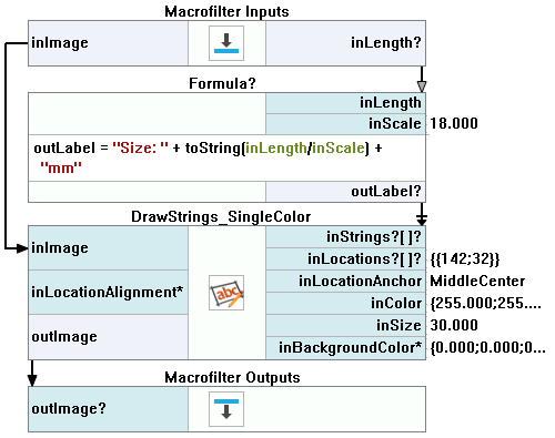
outLabel = "Size: " + toString(inLength/inScale) + "mm"
This formula calculates the object width in millimeters and converts the result to human-readable text.
-
Add the filter DrawStrings_SingleColor to draw the calculated width on the input image.
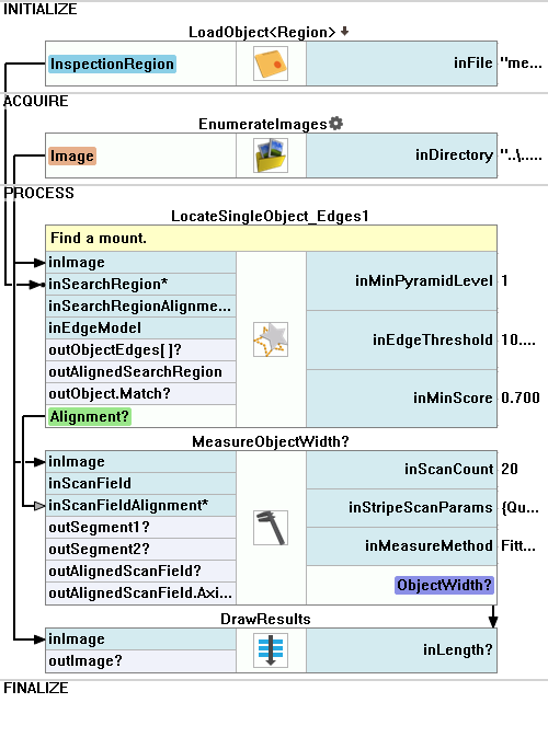
Macrofilter Main finds object and calculates object's width.
Macrofilter DrawResults draws measured width on the input image.
Further Readings
- Template Matching - Most detailed description of the Template Matching technique.