
You are here: Start » Program Examples » Perforated Metal Measurements
Perforated Metal Measurements
Aim:
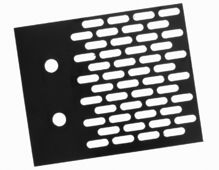
The aim of this application is to measure a perforated metal plate and its holes.
Input:
An image of a plate. The location and orientation of the object are variable.
Output:
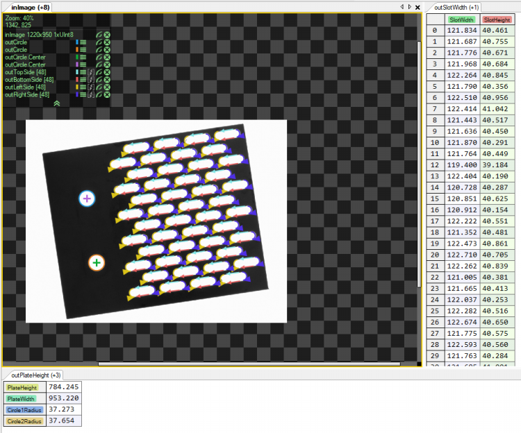
The marked holes, the dimensions of the holes, and the plate.
Hints:
To find the object and the holes position, the Template Matching method can be used. To measure an element, you can use MeasureObjectWidth.
Solution (AVS):
-
In Workspace Explorer, open the workspace Examples, and in the Filmstrip window, select the PerforatedMetal dataset. Drag the Image channel to the ACQUIRE section.
-
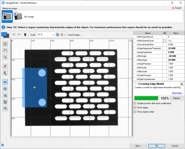
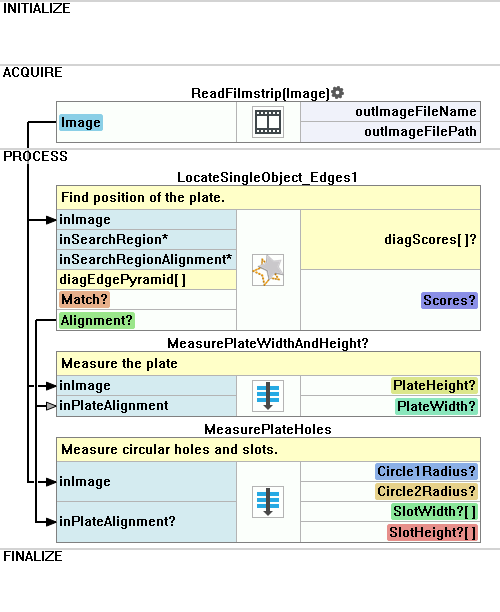
Add the LocateSingleObject_Edges1 to find the plate position:
- Open the inEdgeModel editor from the Properties window, mark the object, and set the parameters as shown on the images below:
- Label the filter outputs:
- The outObject.Match as Match.
- The outObject.Alignment as Alignment.
- The outObject.Score as Scores.
- Open the inEdgeModel editor from the Properties window, mark the object, and set the parameters as shown on the images below:
-
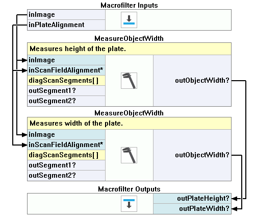
In the Project Explorer create a new Step macrofilter and name it MeasurePlateWidthAndHeight. Drag it to the Process section.
- Create the inImage input and connect it to the ReadFilmstrip.
- Create the inPlateAlignment input and connect it to the Alignment.
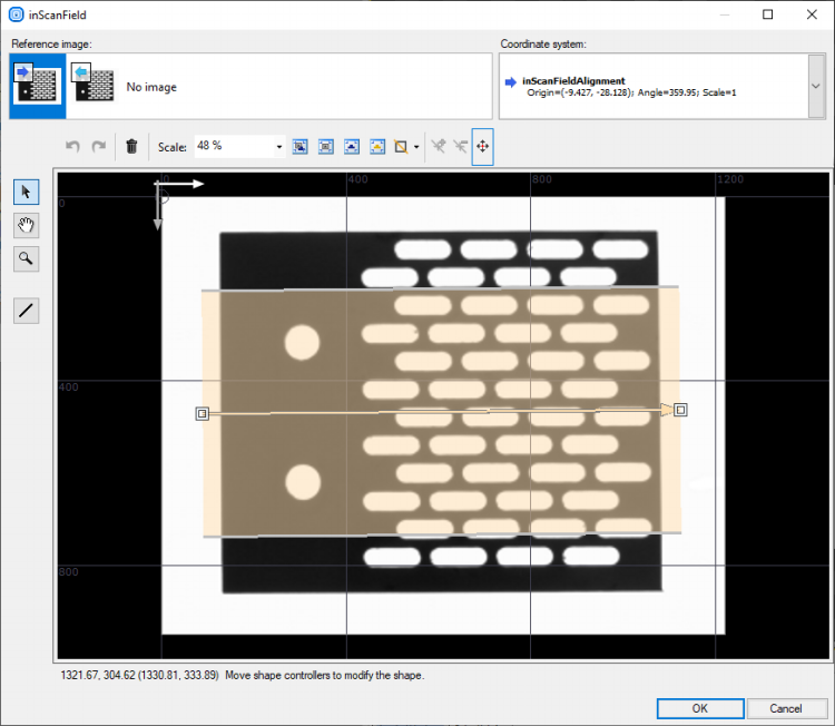
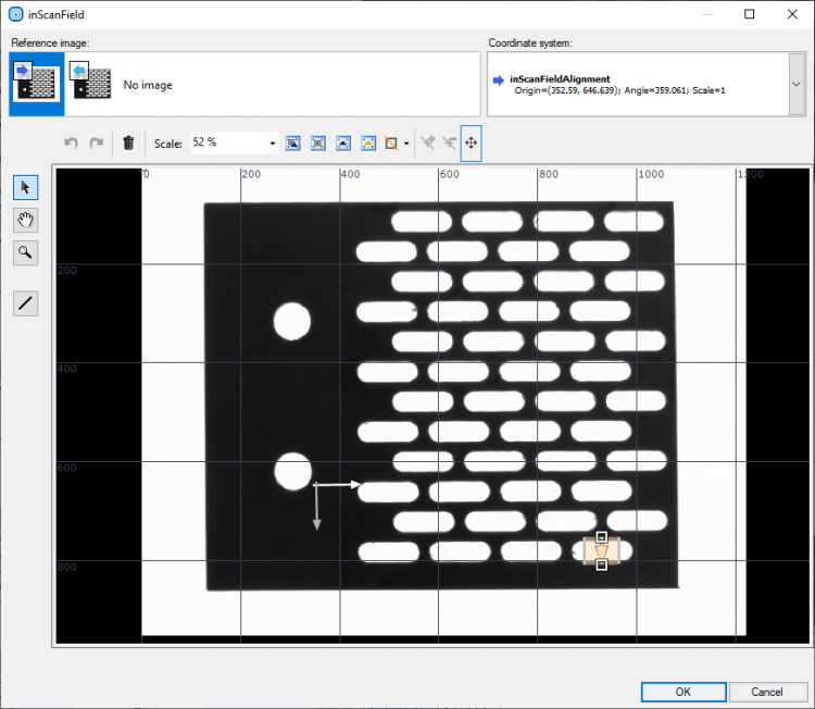
- Inside the Step add 2 MeasureObjectWidth filters. They will be used to measure the height and the width of the plate. Connect their inImage to the Step inImage input and their inScanFieldAlignment to the Step inPlateAlignment input.
- In the first MeasureObjectWidth Properties:
- Set the inScanField as shown on the picture below:
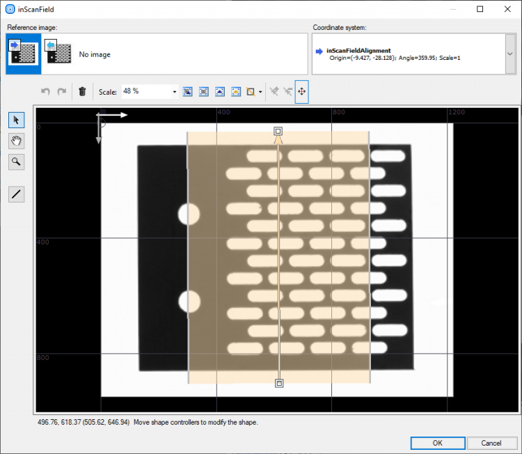
- Set the inScanCount to 20.
- Set the inStripeScanParams inMinStripeWidth to 760.
- Set the inOutlierCount to 10.
- Connect its output as the macrofilter output and name it PlateHeight.
- Set the inScanField as shown on the picture below:
- In the second MeasureObjectWidth Properties:
- Set the inScanField as shown on the picture below:
- Set the inScanCount to 20.
- Set the inStripeScanParams inMinStripeWidth to 930.
- Set the inStripeSelection to First.
- Set the inOutlierCount to 10.
- Connect its output as the macrofilter output and name it PlateWidth.
- Set the inScanField as shown on the picture below:
-
Return to the Main macrofilter. Label the MeasurePlateWidthAndHeight outputs as the PlateHeight and PlateWidth.
-
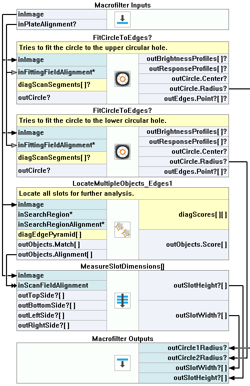
In the Project Explorer create a new Step macrofilter and name it MeasurePlateHoles. Drag it to the Process section.
- Create the inImage input and connect it to the ReadFilmstrip.
- Create the inPlateAlignment input and connect it to the Alignment.
-
Inside the MeasurePlateHoles Step:
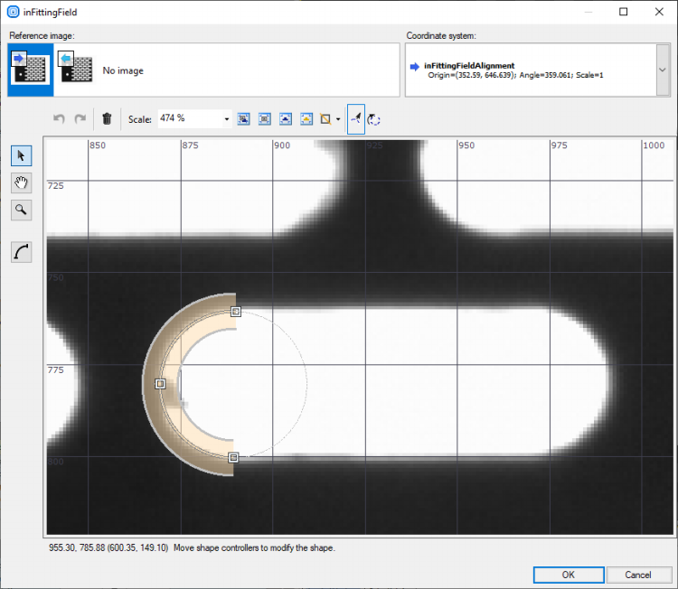
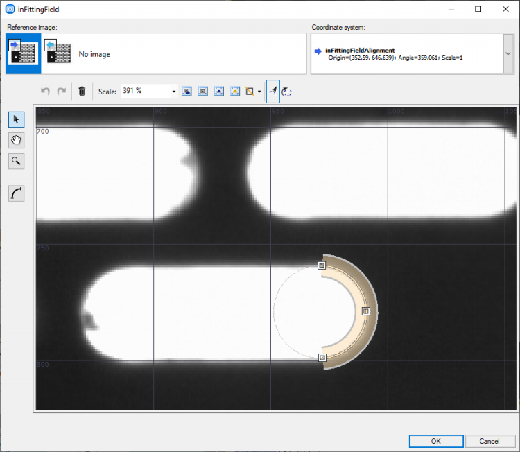
- Add 2 FitCircleToEdges macrofilters. Connect their inImage inputs to the macrofilter inImages input and their inFittingFieldAlignment to the inPlateAlignment.
- In their Properties set the inFittingField as shown in the pictures below:
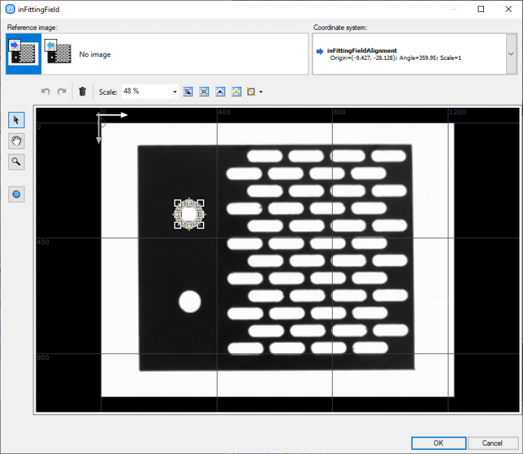
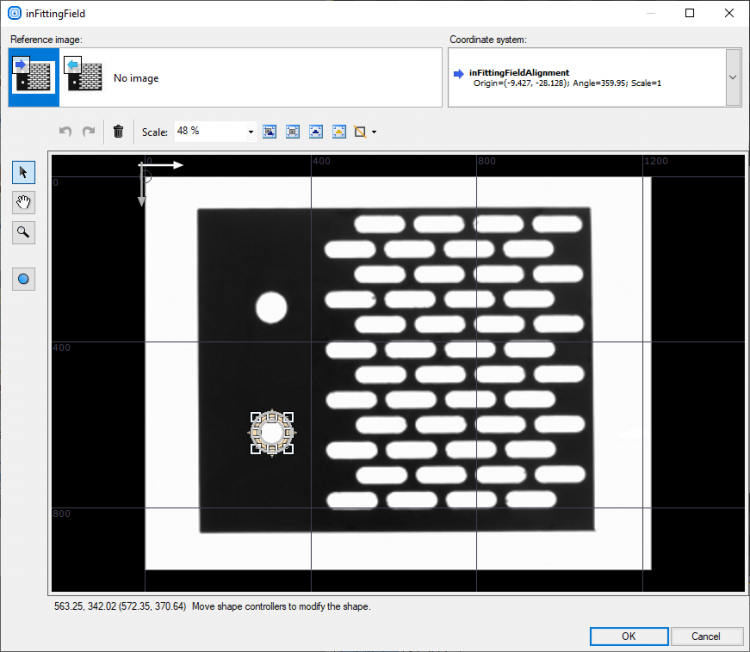
- Drag their outCircle.Radius to the MeasurePlateHoles outputs, name the created outputs as outCircle1.Radius and outCircle2.Radius.
- Add the LocateMultipleObjects_Edges1 to find all slots:
- Connect its inImage input to the MeasurePlateHoles inImage input.
- Set the inEdgeModel as shown in the picture below:
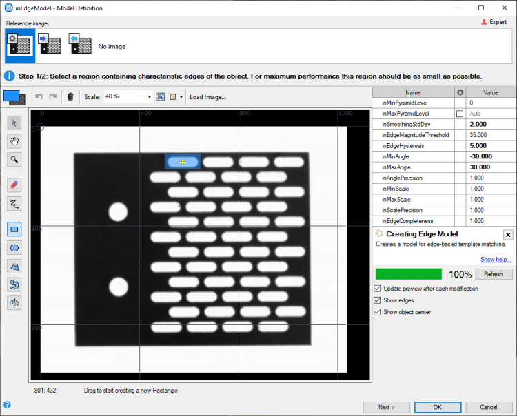
- Set the inMinScore to 0.8.
- Set the inMinDistance to 50.
-
Create a new Step macrofilter, name it MeasureSlotDimensions and drag it inside the MeasurePlateHoles.
- Create the inImage input, connect it to the MeasureSlotDimensions inImage.
- From the LocateMultipleObjects_Edges1 drag the outObjects.Alignment to the new Step and name the new input inScanFieldAlignment.
-
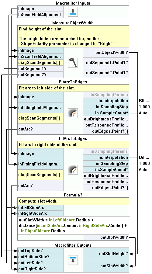
Inside the MeasureSlotDimensions:
- Add the MeasureObjectWidth, connect it to the macrofilter's inputs, set the inStripeScanParams StripePolarity to Bright. Set the inScanField as shown in the picture below:
- Drag the outObjectWidth to the macrofilter's output, name the new output outSlotHeight.
- Drag the outSegment1 to the macrofilter's output, name it outTopSide.
- Drag the outSegment2 to the macrofilter's output, name it outBottomSide.
- Add 2 FitArcToEdges filters, connect their inImage and inFittingFieldAlignment inputs to the macrofilter's inputs. Set their inFittingField as shown in the pictures below:
-
Connect both outArc outputs to the macrofilter's outputs, name them outLeftSide and outRightSide
-
To measure the slot width, use a formula:
- Connect both outArc outputs to the Formula to create inputs, name them inLeftSideArc and inRightSideArc
outSlotWidth = inLeftSideArc.Radius + distance(inLeftSideArc.Center, inRightSideArc.Center) +inRightSideArc.Radius
- Connect the Formula output to the macrofilter's outputs, name it outSlotWidth.
- Add the MeasureObjectWidth, connect it to the macrofilter's inputs, set the inStripeScanParams StripePolarity to Bright. Set the inScanField as shown in the picture below:
-
Return to the MeasurePlateHoles macrofilter. Drag the outSlotHeight and the outSlotWidth from the MeasureSlotDimensions to the macrofilter's outputs, leave the defaults names.
-
Return to the Main macrofilter. Label the MeasurePlateHoles outputs as: Circle1Radius, Circle2Radius, SlotWidth and SlotHeight.
Macrofilter Main.
Macrofilter MeasurePlateWidthAndHeight.
Macrofilter MeasurePlateHoles.
Macrofilter MeasureSlotDimensions.
Further Readings
- Formulas - Detailed information about using formulas.
- Shape Fitting - This article presents usage of the Shape Fitting technique.