
You are here: Start » Program Examples » Hand-Eye Calibration - Editor
Hand-Eye Calibration - Editor
Aim:
The goal is to perform a Hand-Eye Calibration using the dedicated editor built into the RectifyImage filter.
Input:
An image of the circular calibration grid.
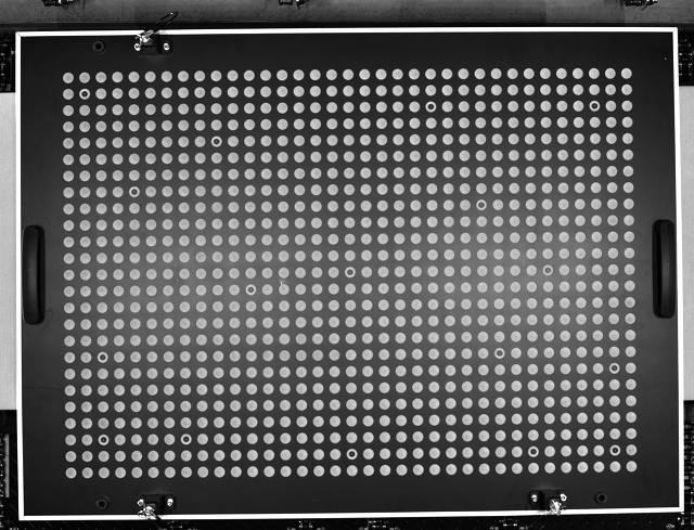
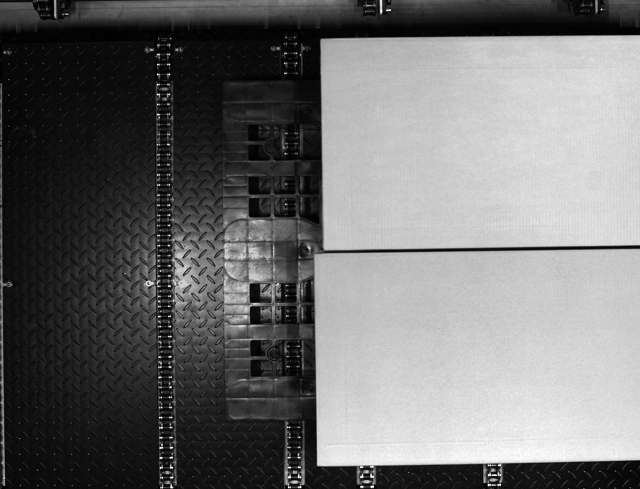
Image with objects.
Output:
Rectified image with world coordinate points.
Hints:
Go through all 3 steps in the calibration editor built into the RectifyImage filter.
Solution (AVS):
-
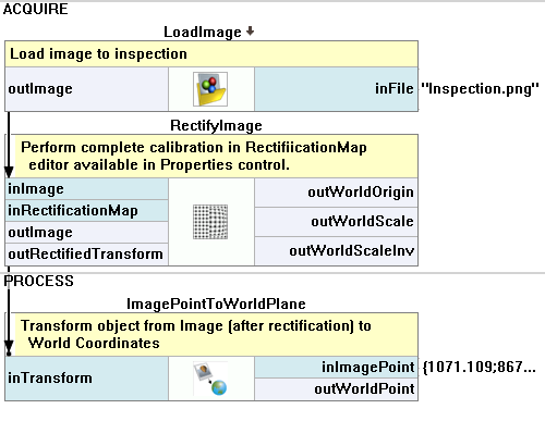
Go to the ACQUIRE section. Add the LoadImage filter and specify the images directory in the inFile.
-
Add the RectifyImage filter and connect the outImage output of the LoadImage filter with the inImage input of the RectifyImage filter.
-
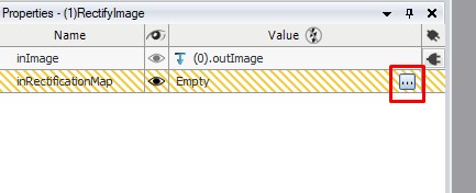
Prepare the inRectificationMap. The dedicated editor can be found in the Properties Window after clicking the three-dot button.
-
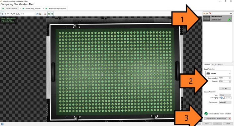
In the first step of the calibration, remove lens distortion:
- Load an image with the calibration grid.
- Use the ruler above the preview to measure the circle radius and enter it in the parameters section.
- Use the Locate button to find calibration circles.
- Calibration will be most precise within the green area. To achieve the best performance across the entire picture, the calibration grid should cover it completely. You can use multiple pictures to achieve this. Just load them into the editor on the right.
- Use the Compute Calibration Model to calculate the Camera calibration model and activate the next step.
-
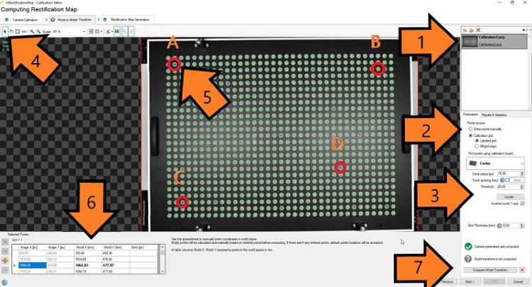
In the second step of the calibration, we will determine the transformation between real-world points and image points:
- Load an image with the calibration grid.
- Choose Calibration grid >> Labeled grid.
- Use the Locate button to find calibration circles.
- Select the black cursor icon.
- Click on point "A" marked with an arrow (5).
- In the table with points insert World X [mm]: 133,64 and World Y [mm]: 493,8.
- Click on point "B".
- In the table with points insert World X [mm]: 1064,83 and World Y [mm]: 477,07.
- Click on point "C".
- In the table with points insert World X [mm]: 172,41 and World Y [mm]: -136,56.
- Click on point "D".
- In the table with points insert World X [mm]: 890,79 and World Y [mm]: 24,28.
- Click the Compute World Transform button.
- Click the Next > button.
-
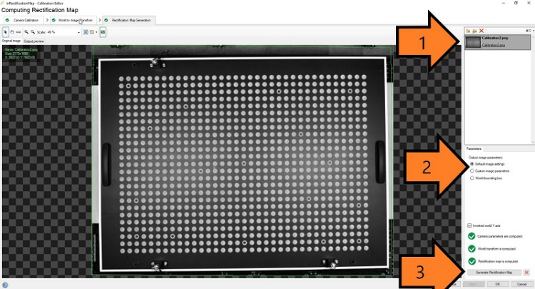
The last step of the calibration is used to set parameters of the image after rectification:
- Load an image with the calibration grid.
- Click the Generate Rectification Map button.
- Click the OK button.
-
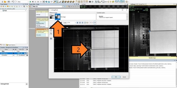
Go back to Main. Image rectification is ready to use. To utilize the created transformation, in the PROCESS section add the ImagePointsToWorldPlane filter to the main program and select the Point variant. Connect the outRectifiedTransform output of the RectifyImage filter with the inTransform input of the ImagePointsToWorldPlane filter.
-
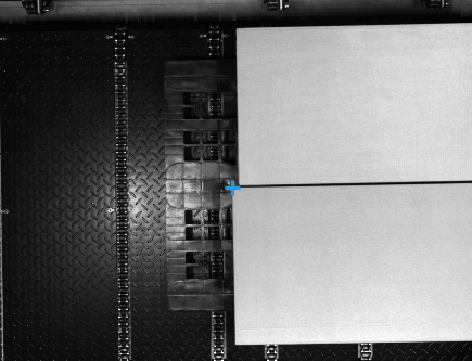
Use the filters' properties and previews to check if the results are correct. Set the inImagePoint as shown in the image below. Make sure to use the rectified image (arrow "1"). Set ImagePoint in one of the box's corners (arrow "2") and click OK.
Macrofilter Main
Used Filters
| Icon | Name | Description |
|---|---|---|
| ImagePointToWorldPlane | Finds the world coordinates of image Point. | |
| LoadImage | Loads a single image from a file. | |
| RectifyImage | Applies a spatial map to distorted image transforming it to rectified image defined in world coordinates. |
Further Readings
- Camera Calibration and World Coordinates - Detailed information about camera calibration and world coordinates.