You are here: Start » Application Notes » Interfacing Zebra 4Sight computer (Modbus TCP - Server) to Aurora Vision Studio
Interfacing Zebra 4Sight computer (Modbus TCP - Server) to Aurora Vision Studio
Purpose and equipment
This document explains how to configure Modbus TCP PLC with Aurora Vision Studio using Zebra 4Sight computer. In this setup, the Zebra 4Sight computer running Aurora Vision Studio acts as a Modbus Slave (Server), while the PLC acts as a Modbus Master (Client).
Required equipment:
- 4Sight computer (used 4Sight XV7);
- Siemens S7-1200 PLC;
- Ethernet switch with at least 3 In/Outs might be useful - simplifies configuration;
- PC with TIA Portal V19 (for PLC configuration);
- Aurora Vision Studio 5.6 or later (version 5.6 used).
Application notes demonstrates configuration steps for specific 4sight model, but it is not obligatory to use this one. If you have different model, please refer to manuals provided by its manufacturer.
Hardware connection
In application notes there is configured one network which uses Ethernet switch. Devices connected to this network have addresses 192.168.1.XXX, where XXX stands for number 1-254 unique for every device/port connected.
In Zebra 4Sight manual it is mentioned that PLC Software should not be installed on Z4Sight PC. Taking this into account, we have one PLC and two computers in our network:
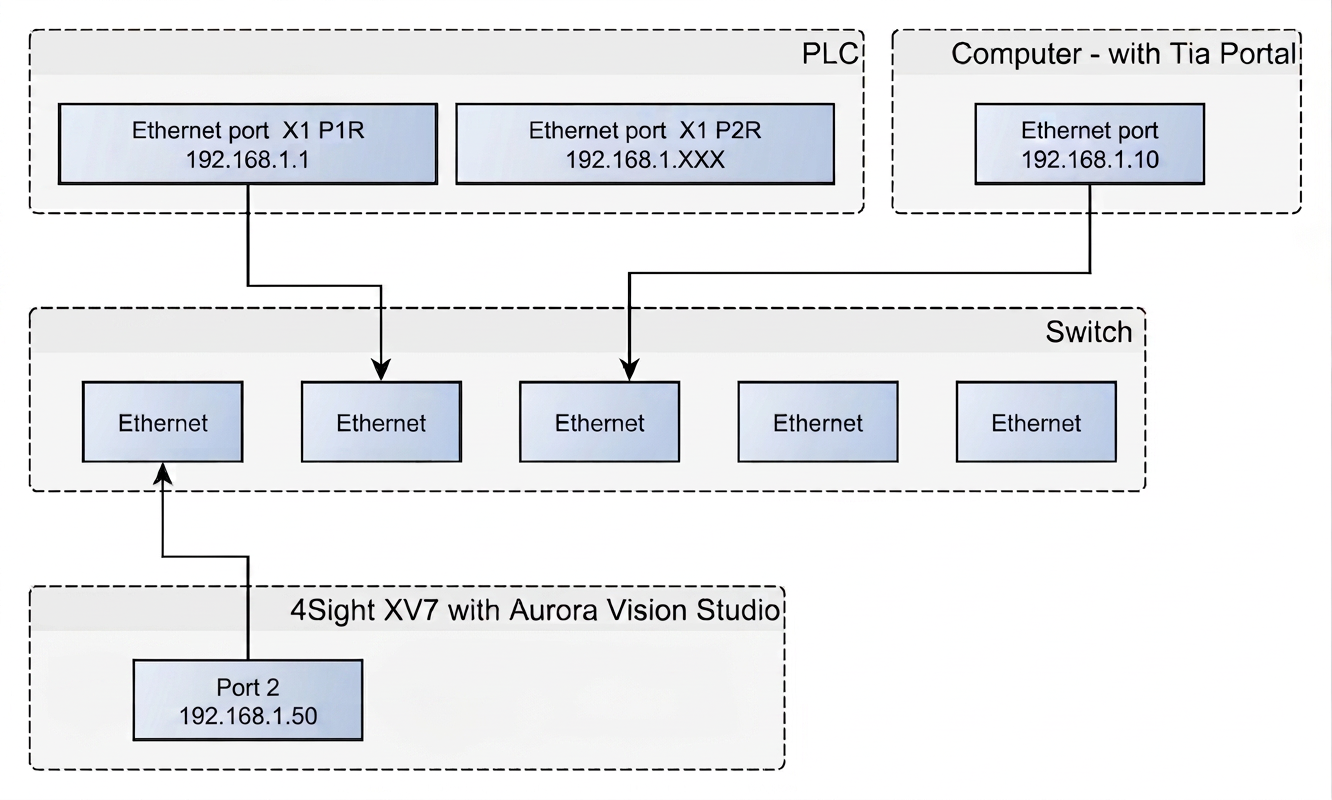 Before proceeding to the further point, make sure that all devices are powered up.
Configuring MIL on Zebra 4Sight
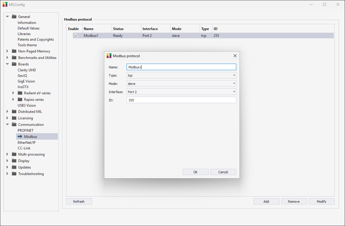
Before creating the application in Aurora Vision Studio, the Modbus slave service must be enabled in the MIL configuration.
- Open the MILConfig application on the Z4Sight computer.
- In the left pane, navigate to Communication -> Modbus.
- Add a new instance. Set parameters:
- Name: Modbus1
- Type: tcp
- Model: slave
- Interface: Port 2
- ID: 255
- Save the configuration
Aurora Vision Studio application
The application utilizes dedicated Z4Sight Modbus filters to read and write holding registers.
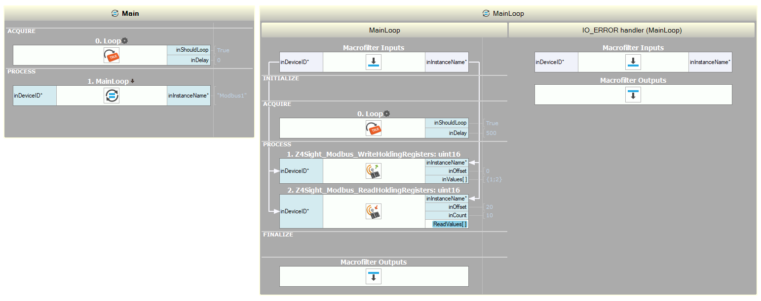
- Inside the Main macrofilter, go to the ACQUIRE section and add a Loop filter to keep the task running continuously.
-
In the PROCESS section, create a new Step Macrofilter named MainLoop. Add two macrofilter inputs:
- inDeviceID of type Z4SightSystemAndDeviceIdentifier*
- inInstanceName of type String*
Set the inInstanceName value to match the MILConfig setup (Modbus1).
- Open the MainLoop macrofilter. In the ACQUIRE section, add the Loop filter. Set its inDelay input to the desired polling rate (e.g., 500 ms) to regulate the communication frequency.
- In the PROCESS section, add the Z4Sight_Modbus_WriteHoldingRegisters_uint16 filter. Link the inDeviceID and inInstanceName from the macrofilter inputs. Set inOffset to 0 and the inValues to {1;2}.
- Add the Z4Sight_Modbus_ReadHoldingRegisters_uint16 filter. Link the inDeviceID and inInstanceName from the macrofilter inputs. Set inOffset to 20 and inCount to 10. Present the outValues in the Preview window.
- In the Project Explorer, right-click on the MainLoop macrofilter block, select Add New Error Handler, and choose IO_ERROR.
Configuring PLC in TIA Portal
Device Configuration
After adding the S7-1200 PLC to the project, apply the following settings in the Properties tab:
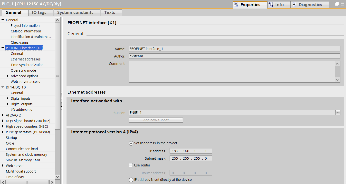
- PROFINET interface [X1]: Set the appropriate IP address and add/setup the Subnet. Ensure it is in the same subnet as the Z4Sight computer.
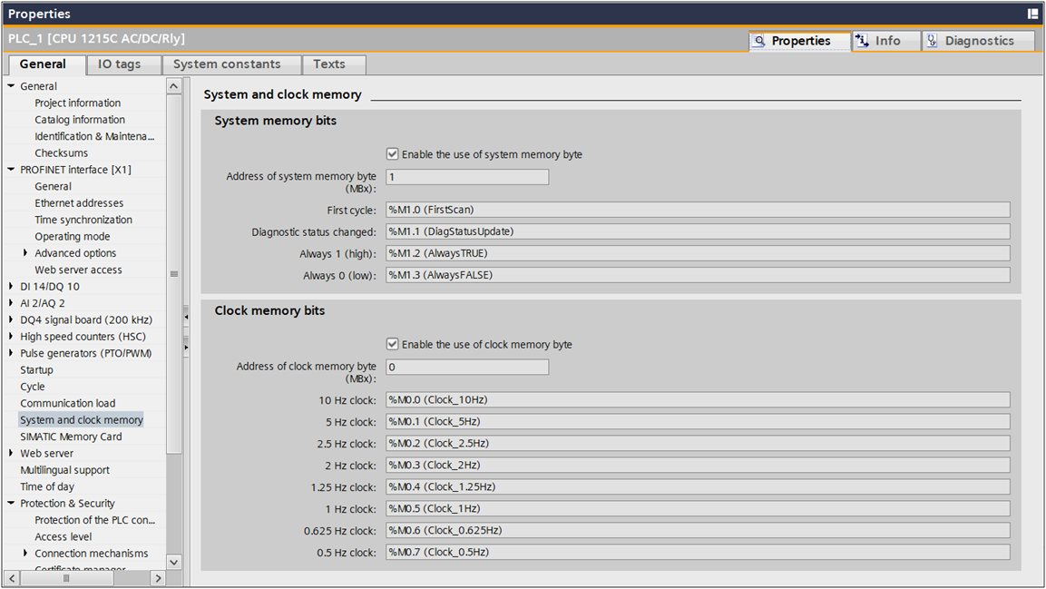
- System and clock memory: Check Enable the use of system memory byte and Enable the use of clock memory byte.
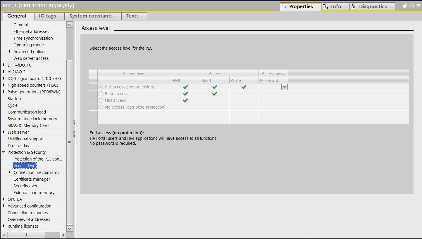
- Access level: Set to Full access (no password).
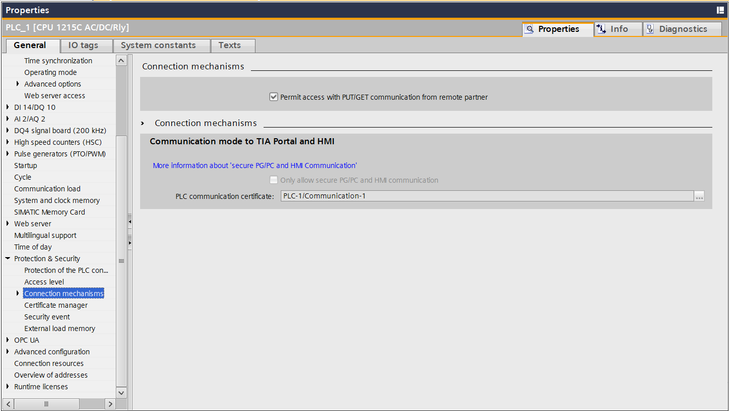
- Connection mechanisms: Check Permit access with PUT/GET communication from remote partner and uncheck Only allow secure PG/PC and HMI communication.
Creating Data Blocks
Two Data Blocks are required to manage the data arrays and the connection parameters:
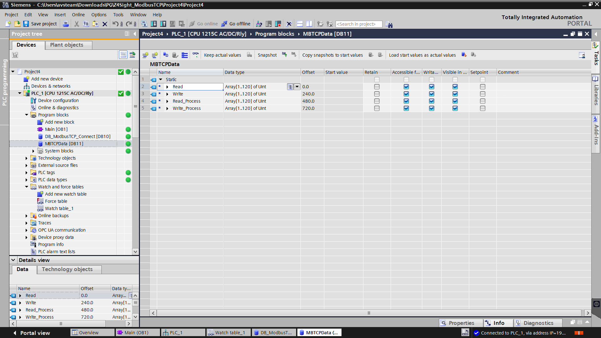
- MBTCPData [DB11] - it holds the raw Modbus arrays and the processed (byte-swapped) arrays.
- Define the following variables:
- Read of type Array[1..120] of UInt (Raw data received from AVS)
- Write of type Array[1..120] of UInt (Raw data to be sent to AVS)
- Read_Process of type Array[1..120] of UInt (Byte-swapped data ready for PLC logic)
- Write_Process of type Array[1..120] of UInt (PLC data before byte-swapping for transmission)
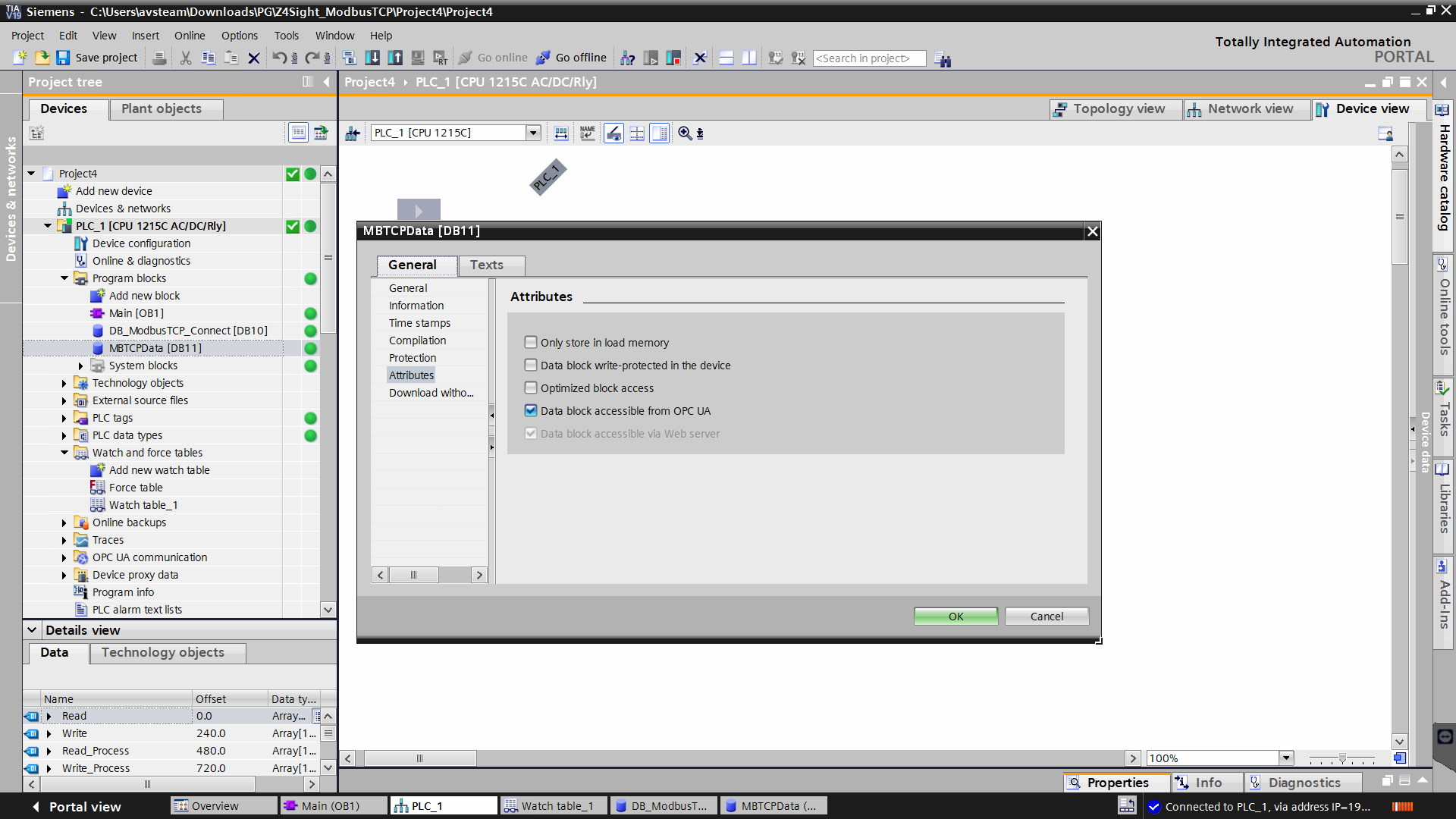
- Right-click the block, go to Properties -> Attributes, and uncheck the Optimize block access option. This is mandatory to expose absolute addressing.
- Define the following variables:
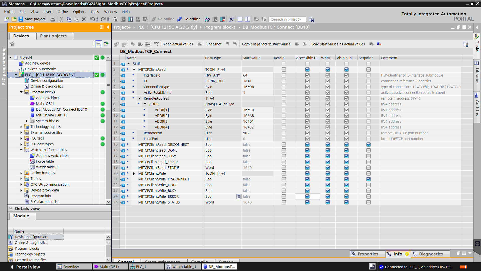
- DB_ModbusTCP_Connect [DB10] - it stores the connection parameters and status flags for both the read and write operations. Set their Start values as follows:
- MBTCPClientRead of type TCON_IP_v4:
- InterfaceId: 64
- ConnectionType: 16#0B
- RemoteAddress: 192.168.1.50 (IP address of the Z4Sight computer)
- RemotePort: 502
- ID: 16#1 (Must be unique and different from the ID set in MILConfig).
- Add Bool flags: MBTCPClientRead_DISCONNECT, MBTCPClientRead_DONE, MBTCPClientRead_BUSY, MBTCPClientRead_ERROR.
- Add MBTCPClientRead_STATUS of type Word.
- Create a corresponding set of variables for MBTCPClientWrite (using a unique ID: 16#2).
- MBTCPClientRead of type TCON_IP_v4:
- MBTCPData [DB11] - it holds the raw Modbus arrays and the processed (byte-swapped) arrays.
Main Logic [OB1]
Create structure as showed in images below:
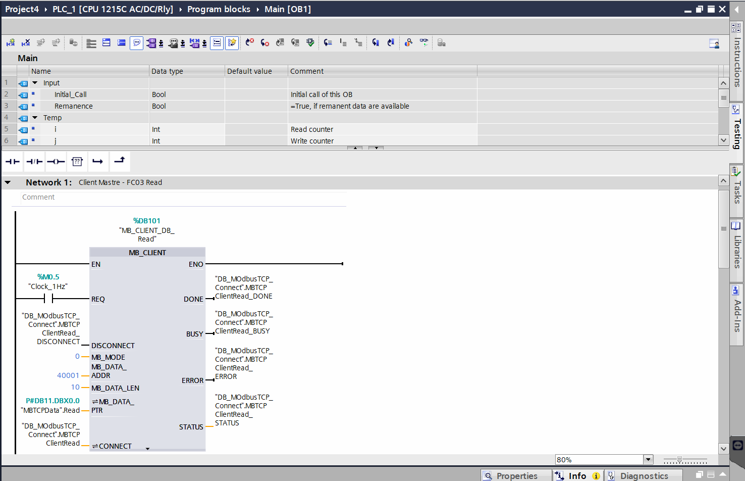
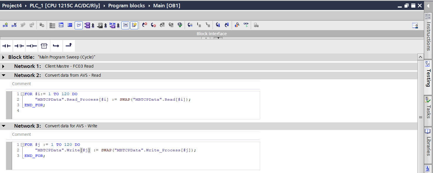
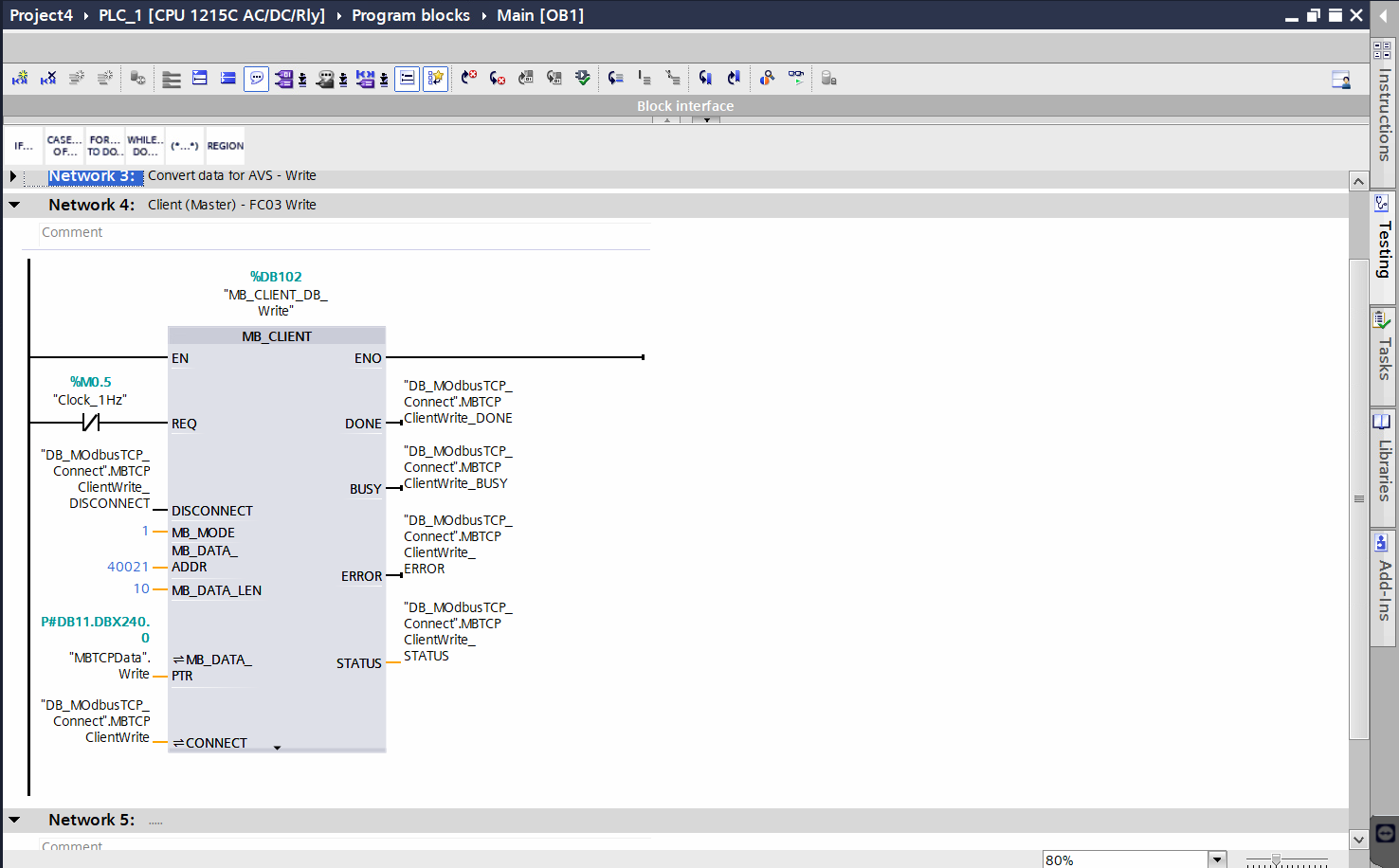
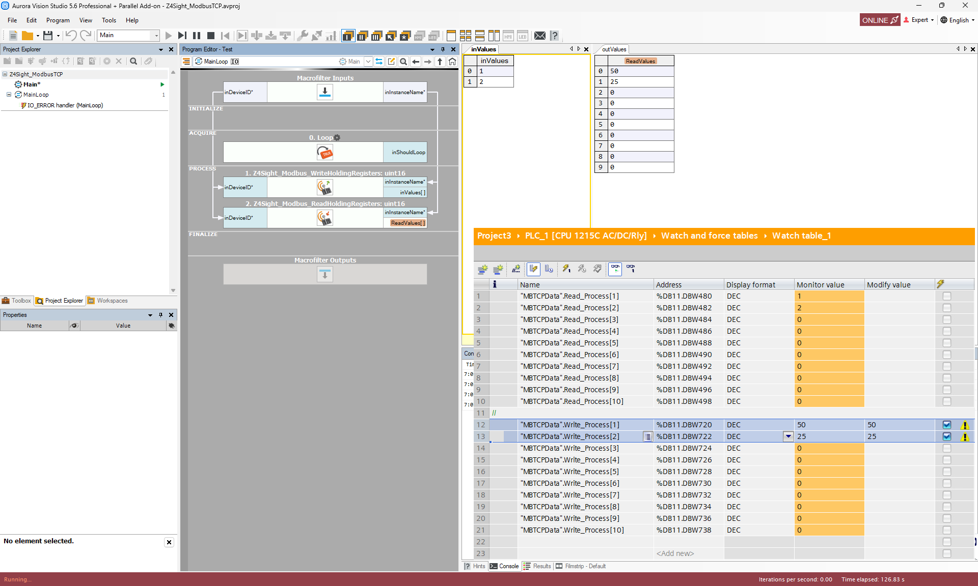
When monitoring values in the TIA Portal Watch Table, always refer to the Read_Process and Write_Process arrays to see the correct decimal values.