You are here: Start » Application Notes » Using Modbus TCP Communication
Using Modbus TCP Communication
Purpose and equipment
This document describes how to make a practical example of establishing Modbus TCP communication between Aurora Vision Studio and a PLC device or a Modbus TCP simulator. Aurora Vision Studio 5.2 and the Simatic S7- 1200 CPU 1212C AC/DC/RLY controller with TIA Portal V15 were used to accomplish this task. For more theoretical background refer to the Working with Modbus TCP Devices entry.
Required equipment:
- Modbus TCP simulator, e.g. EasyModbusTCP
- SIMATIC S7-1200 or other controller from the SIMATIC S7 family
- TIA Portal V15
- Aurora Vision Studio 5.0 Professional or later (version 5.2 was used)
Overview and first steps
In this example, you will create two versions of the application, basic and advanced:
- the basic version of the application does not require a PLC; a Modbus TCP simulator can be used instead. This program enables exchanging basic data types between the Aurora Vision Studio client and the Modbus TCP server (PLC or a simulator);
- the advanced version of the application requires additional logic to be implemented in the PLC program. It simulates a dynamic mathematical model which represents a heater: a user can change parameters of the model parameters so the object can react slower or faster. A user can manually modify the model input parameters which represent the voltage fed to the actuator device. The PLC sends feedback about the temperature level which is then shown on the HMI;
First, you need to establish a hardware connection between the PLC or the PLC simulator and the PC. The network configuration will be described later in this entry.
Basic program with Modbus TCP simulator
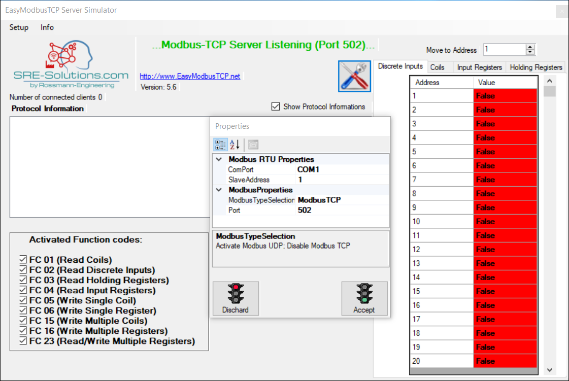
Open the EasyModbusTCP simulator and press the Setup button in the lower left corner of the application window. A Properties window will pop up: follow the image below to set up the configuration:
Then open a new Aurora Vision Studio project, add the ModbusTCP_Connect filter to the INITIALIZE section and the ModbusTCP_Close filter to the FINALIZE section. Aurora Vision Studio provides a set of ready-to-use filters for communication over the ModbusTCP protocol. A full list of the relevant filters is available here.
Add a Task Macrofilter to the PROCESS section.
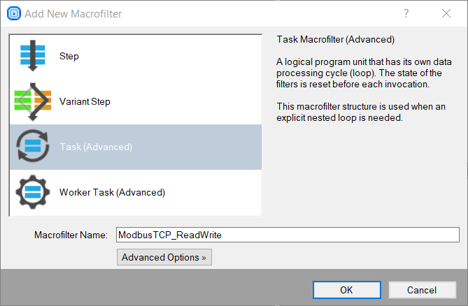
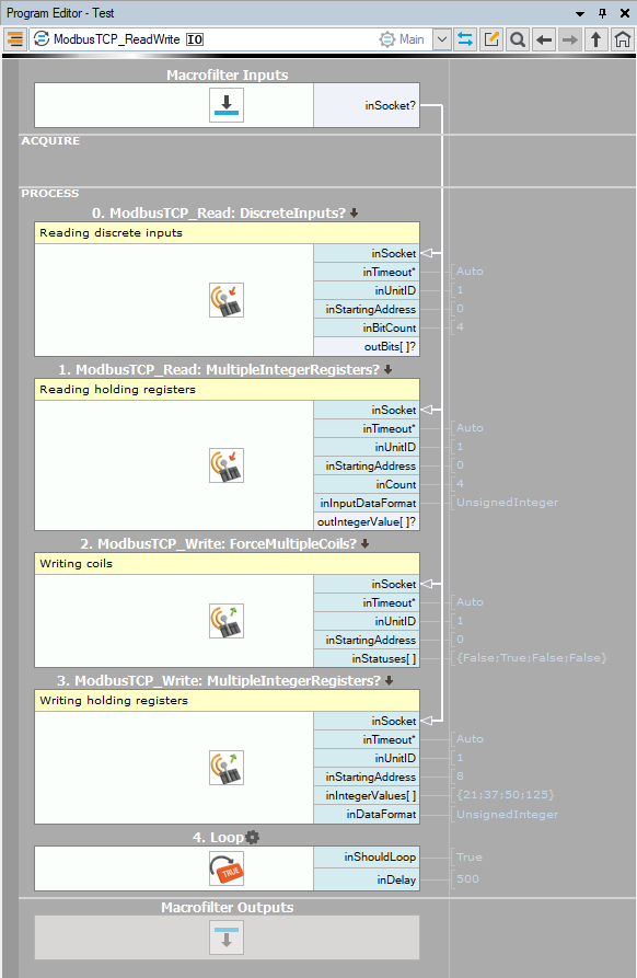
Open the newly created Task Macrofilter and add the ModbusTCP_ReadDiscreteInputs, ModbusTCP_ReadMultipleIntegerRegisters, ModbusTCP_ForceMultipleCoils and ModbusTCP_WriteMultipleIntegerRegisters filters in the arrangement simulating that in the image below:
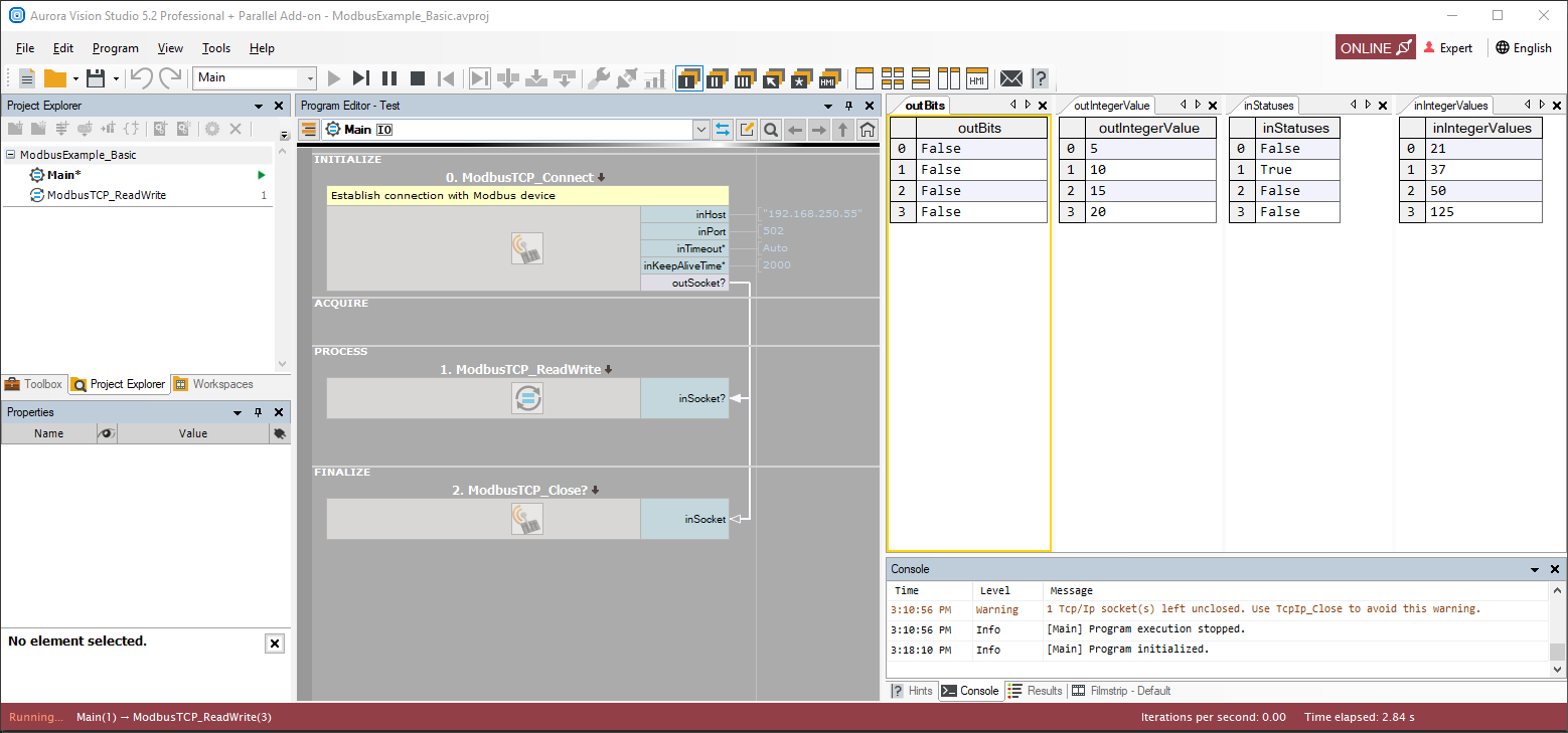
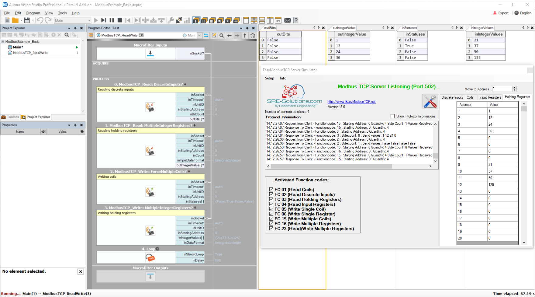
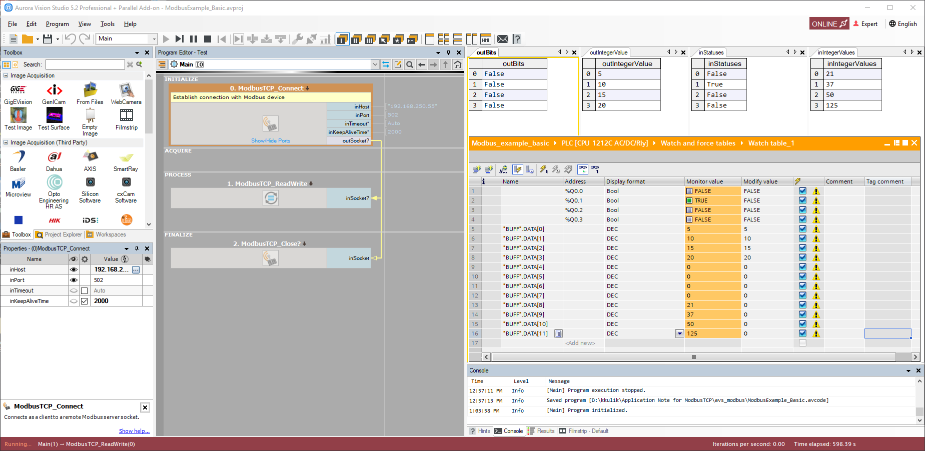
Below you can see working communication between the ModbusTCP client within the Aurora Vision Studio application and the simulated server.
Basic program with a PLC
Network configuration
Main network configuration
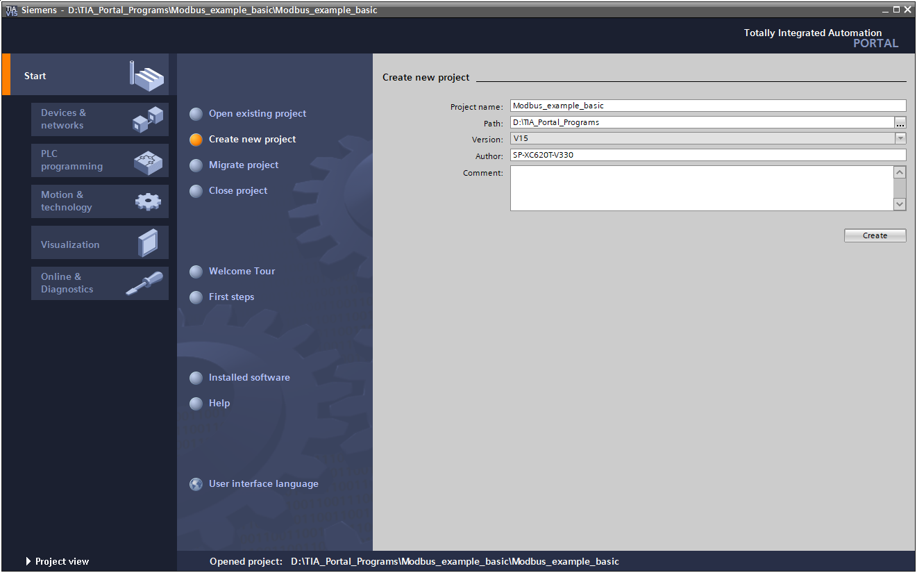
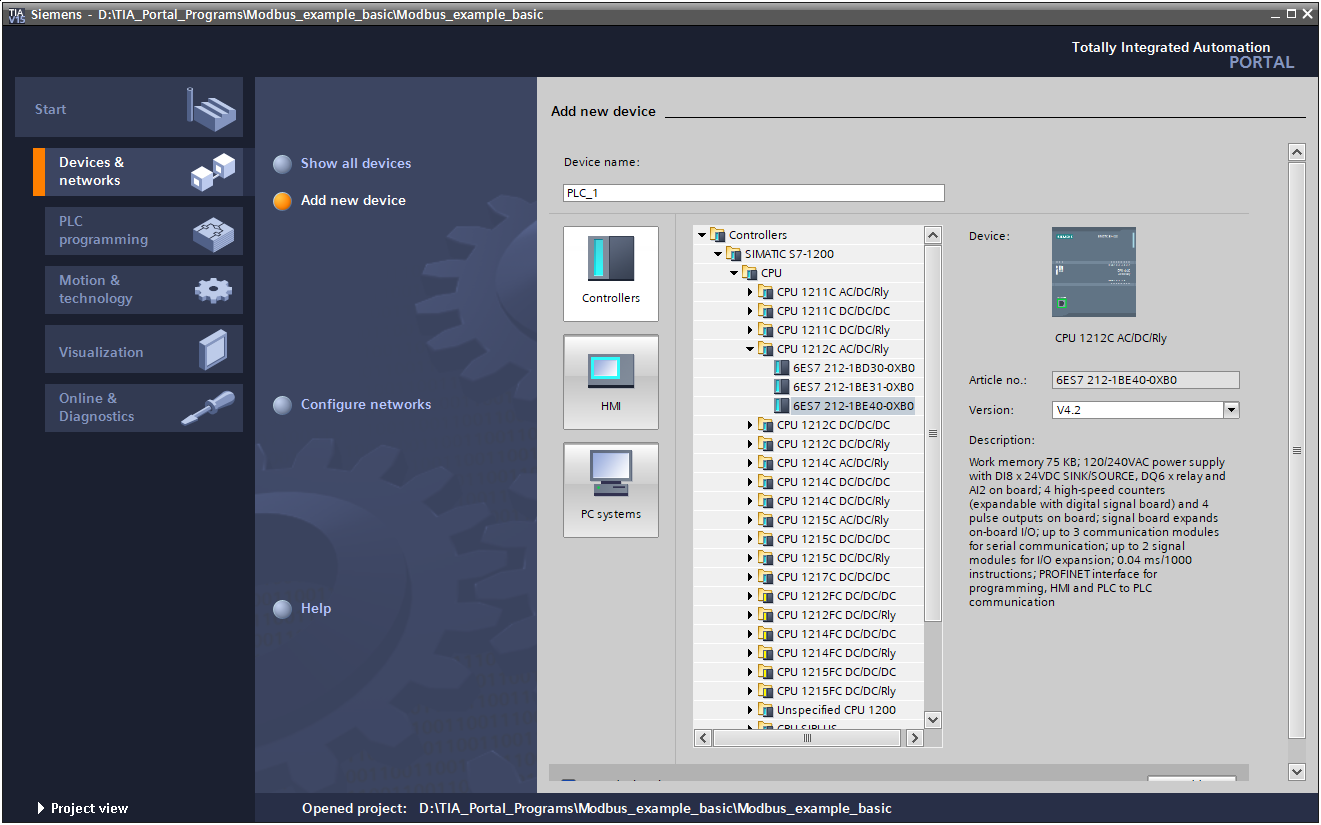
Create a new project in the TIA Portal environment and add your device by double-clicking on the Add new device button. Select your controller model, set its CPU and other available components listed in the drop-down menu. Once you are ready, click the OK button.
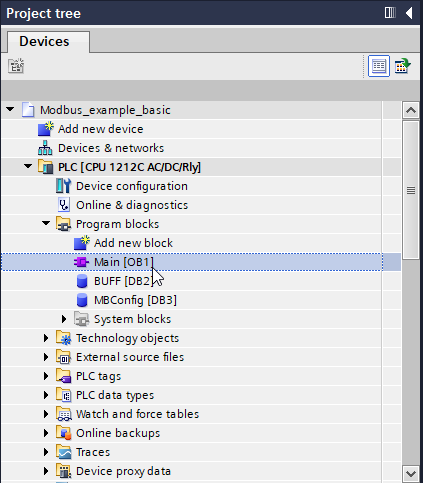
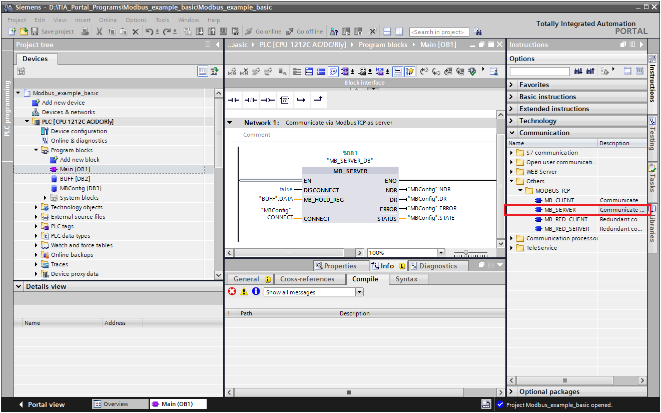
Expand the Program blocks list and double-click the Main icon. A network view will appear. Expand the Communication tab on the right-hand side (within the Instructions section) and double-click on the MB_SERVER icon available at the Communication -> Others -> MODBUS TCP location.
Drag the MB_SERVER block from the Communication -> Others -> MODBUS TCP location and drop it on to Network 1 within the application Basic.
Troubleshooting IP addressing
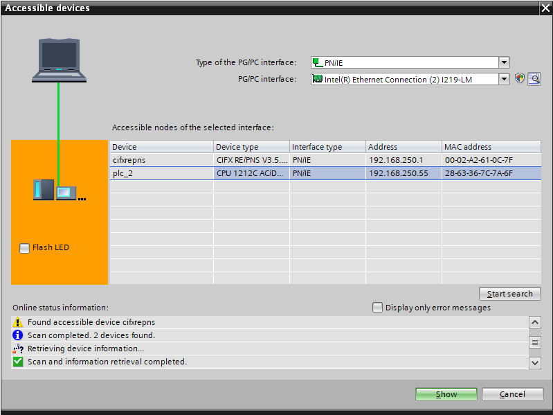
Select the Accessible devices icon from the toolbar to open the configuration window. Select the PN/IE type of the PG/PC interface and then the Ethernet card connected to the PLC. Click the Start search button, choose your PLC from the list of accessible nodes and click the Show button.

Creating a PLC program
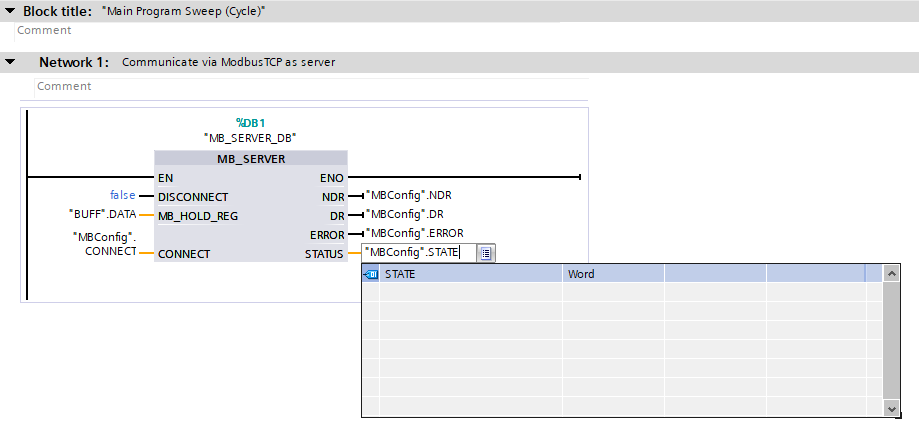
This chapter describes how to create a PLC program to establish communication. The basic application that we start out with has only one function block; it is the same one that was created in the previous section:
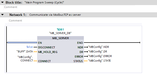
The MB_SERVER instruction is used to establish the Modbus TCP communication. In the image above, you can see some DB blocks connected to several inputs and outputs of the MB_Server block. In order to establish communication between a client and the server, you will need to set them up according to the way presented below:
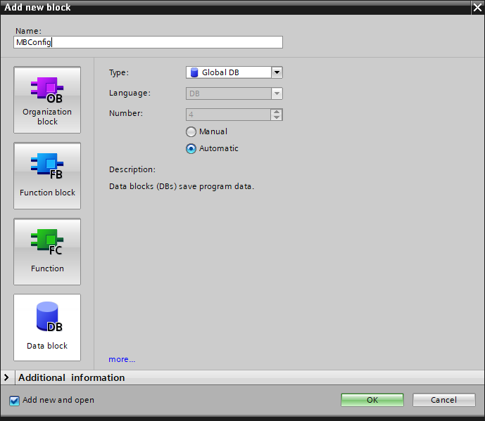
- MBConfig - DB block which defines the connection type, the address of the ModbusTCP server as well as the used Port (by default 502)
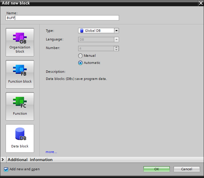
- BUFF - DB block serving as the communication buffer for the data received or sent between the PLC and the Aurora Vision Studio application
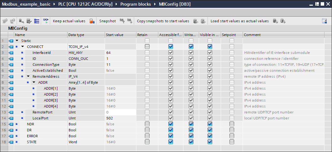
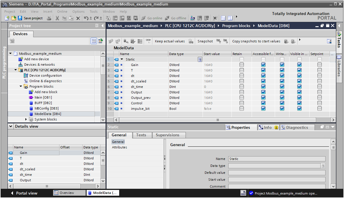
Now, define variables in the Data block. Use the same names and data types as in the image below. If you want to create a new row, just right-click on any row and select Insert row. Note that setting the right values of the Start values is essential in this step.
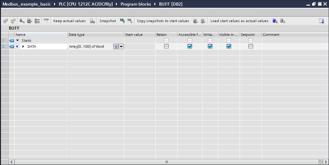
Create a word array in the BUFF data block, it should have the same size as it does in the image below:
Attach the data block variables to the inputs and outputs of the MB_SERVER block in the way presented below:
If all previous steps have been performed correctly, your PLC program is ready. Compile the application and download it to the device. To see the current states of variables, turn on the Monitoring mode:


Use the application created in Aurora Vision Studio in the section where the Modbus TCP simulator was used. To test discrete inputs, coils and registers in TIA Portal, create a Watch table and a Force table, like in the image below:
Advanced program with a PLC
Creating a PLC program
This chapter describes how to modify a basic PLC program to meet requirements of advanced usage as mentioned at the beginning of this article. If you have created a Basic PLC program described in the previous chapters, save this project as a copy with a new name. Otherwise, create BUFF and MBConfig data blocks as described in this section.
Create a new Data block called ModelData with the variables set like in the image below:
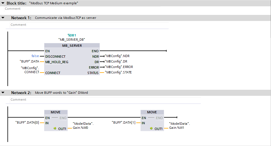
Nothing has changed for Network 1 of the Advanced program; MB_SERVER block is used to establish the Modbus TCP connection. For Network 2 use MOVE blocks to move appropriate BUFF data words to the ModelData.Gain variable.
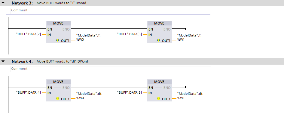
For Networks 3 and 4, use MOVE blocks to move BUFF words to ModelData.T and ModelData.dt.
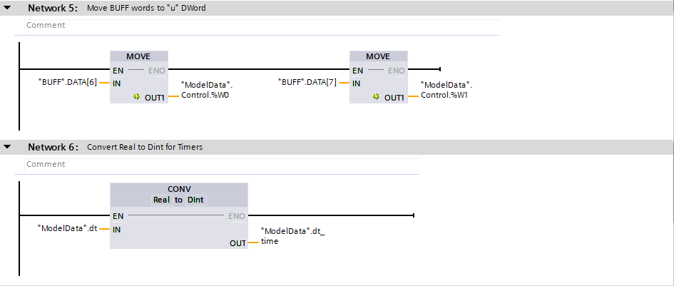
For Network 5, use MOVE blocks to move BUFF words to ModelData.Control. For Network 6, use a CONV block to convert Real values to Dint values for further use in timers blocks.
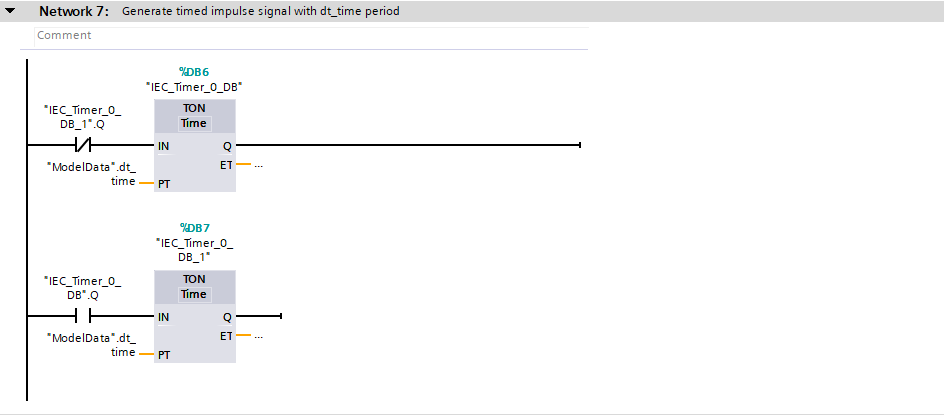
Network 7 uses TON Timer blocks to generate a timed impulse signal for further calculations. Create a new branch in this network, put TON blocks in the network and create Data blocks appropriate for them.
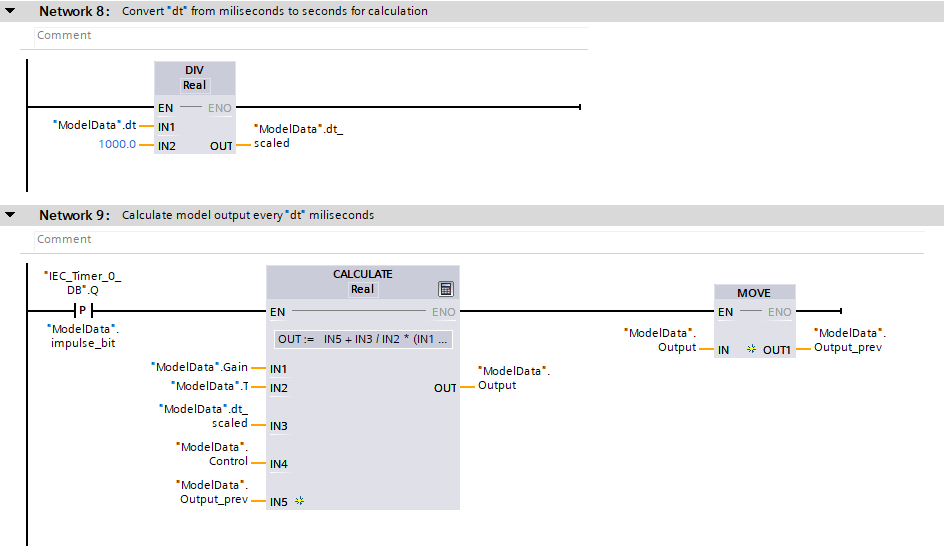
For Network 8, use a DIV block to scale ModelData.dt from milliseconds to seconds for further calculations. For Network 9, use the logic presented in the image below. The formula for the CALCULATE block should be as follows:
OUT:= IN5 + IN3 / IN2 * (IN1 * IN4 - IN5)
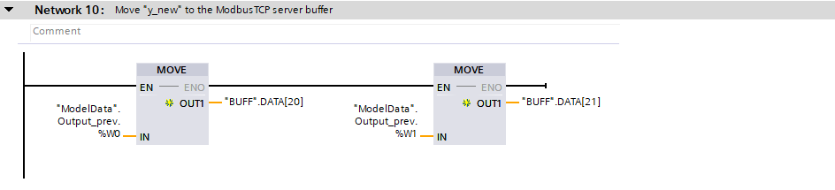
For Network 10, use MOVE blocks to move ModelData.Output_prev words to BUFF. This variable will be read in Aurora Vision Studio application.
Creating Aurora Vision Studio program
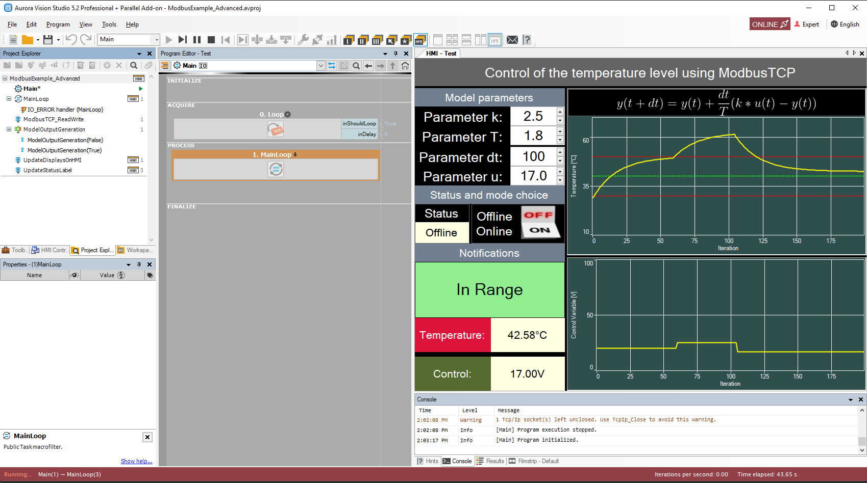
This Application Note does not explain how to create an HMI for an advanced program example. Take a look at the official Aurora Vision Studio example ModbusExample_Advanced.
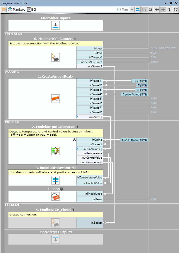
The MainLoop macrofilter body which is iterated every 200 ms:
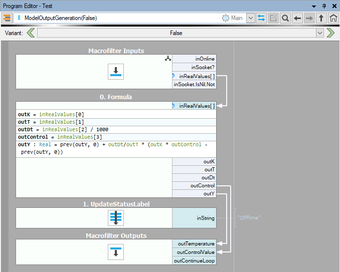
The False branch of the ModelOutputGeneration variant macrofilter:
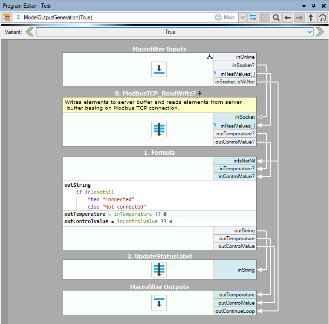
The True branch of the ModelOutputGeneration variant macrofilter:
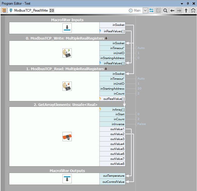
The ModbusTCP_ReadWrite macrofilter which is invoked in the online mode:
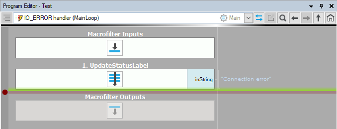
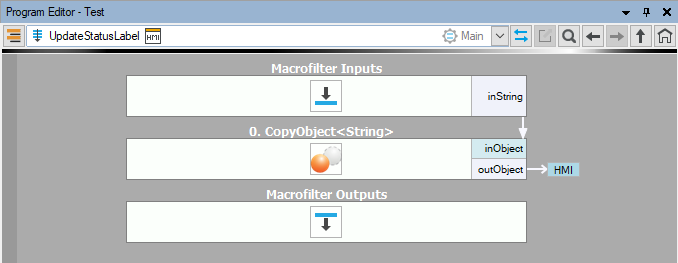
The UpdateStatusLabel macrofilter which is invoked in a few parts of the program; for instance, to notify the user about successful execution or an upcoming error:
An IO_ERROR error handler which is executed when connection in the online mode is interrupted: