
You are here: Start » Application Notes » Hardware Triggering Zebra CV60 Camera using Zebra 4Sight EV7 Auxiliary Outputs
Hardware Triggering Zebra CV60 Camera using Zebra 4Sight EV7 Auxiliary Outputs
1. Introduction
The aim of this application note is to demonstrate how to configure and use the auxiliary output signals of a vision controller to perform hardware triggering on an area scan camera. By the end of this guide, you will be able to set up an automated hardware trigger loop using the Zebra 4Sight EV7 vision controller to capture images synchronously on a Zebra CV60 Area Scan Camera.
Required Hardware and Software:
- Zebra 4Sight EV7 Vision Controller
- Zebra CV60 Area Scan Camera
- 24V DC Power Supply
- Aurora Vision Studio software
2. Connecting the Devices
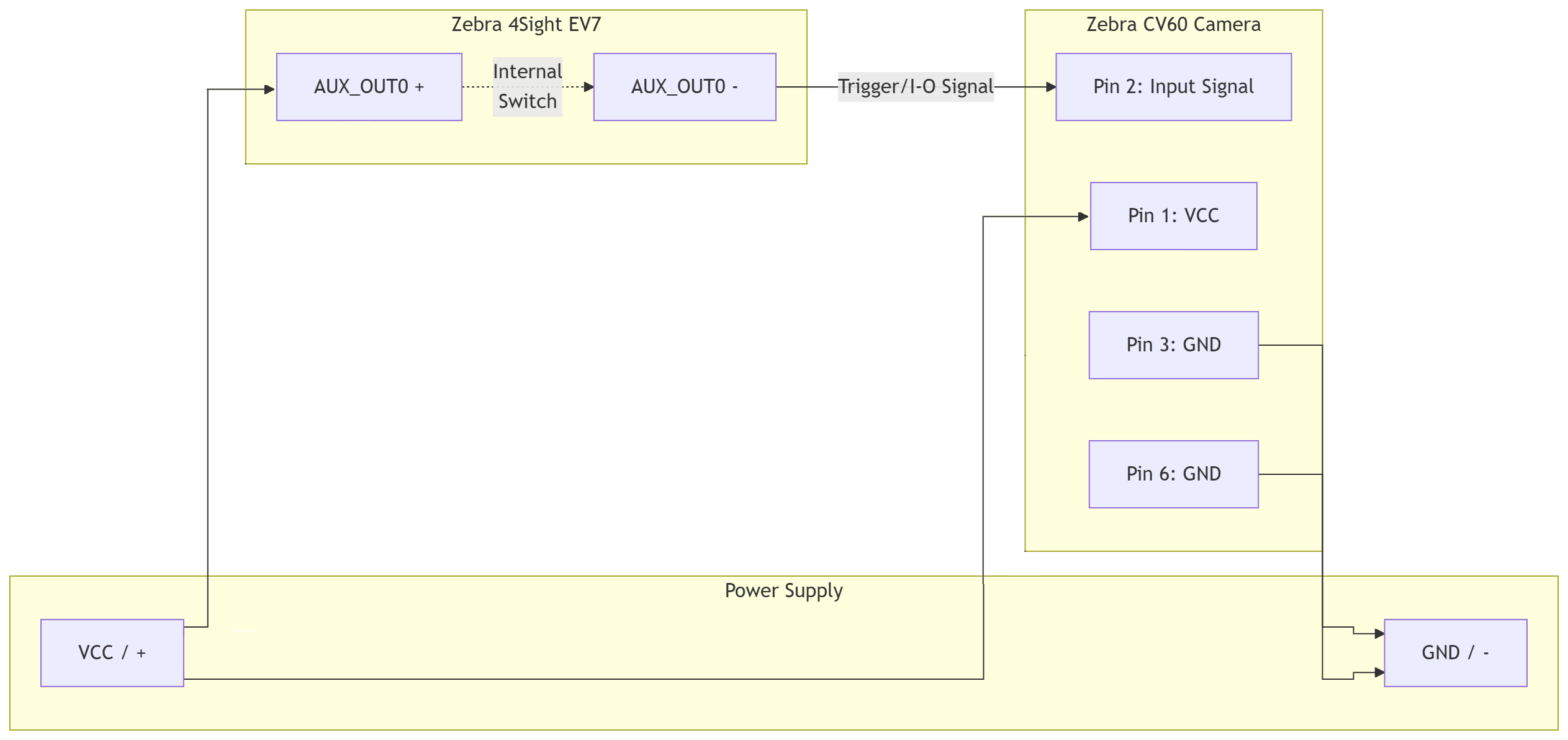
Before creating the software application, the hardware must be wired correctly. Based on the Zebra 4Sight EV7 Product Reference Guide and CV60 Area Scan Camera documentation, wire the devices as follows:
- Parallel VCC Connection:
- The Supply Voltage (VCC, 24V) is fed to Pin 1 of the CV60 camera (main power and I/O reference).
- Simultaneously, VCC is connected to AUX_OUT0+ on the EV7 controller.
- Signal Reception (CV60):
- The current sourced from
AUX_OUT0-enters Pin 2 of the CV60 camera.
- The current sourced from
- Circuit Return (GND):
- Pin 3 and Pin 6 of the CV60 camera must be tied to the common power supply ground (GND). This completes the circuit for both the camera's main power and the opto-isolated input return path.
3. Creating the Application in Aurora Vision Studio
With the hardware wired, we will now create an application that periodically toggles the EV7 output to trigger the camera, while a separate background task handles the image acquisition.
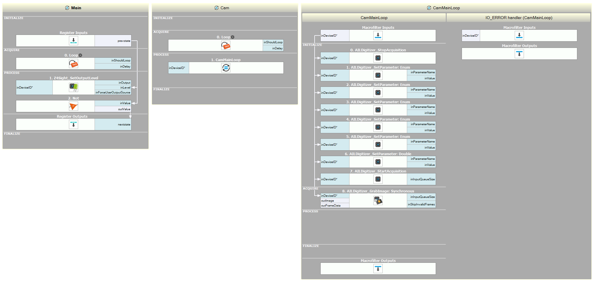
Part A: Configuring the Output Signal (Main Task)
This section of the program will act as our trigger generator, toggling the output state.
- In the
Mainmacrofilter, add a Loop filter to the ACQUIRE section. Set theinDelayinput to1000(milliseconds). - Add a Z4Sight_SetOutputLevel filter in the PROCESS section.
- Set the
inDeviceIDinput to"Host"and"Default". - Set the
inForceUserOutputSourceinput toTrue.
- Set the
- In the Project Explorer window, right-click on the
Mainmacrofilter and choose the "Add macrofilter register" option. Name the new register"state"and set its type toBool. Set its initial value toTrue. - Connect
prev statefrom the Macrofilter Register Inputs block to theinLevelinput of the Z4Sight_SetOutputLevel filter. - Add a Not filter to the PROCESS section.
- Connect its input to
prev statefrom the Register Inputs. - Connect its output to
next stateon the Register Outputs block.
- Connect its input to
Part B: Configuring the Camera Acquisition (Worker Task)
Image grabbing must run independently of our 1-second trigger loop, so we will place it in a Worker Task.
- Create a new Worker Task macrofilter. Name it
"Cam". - Inside the
"Cam"worker task, add a Loop filter to the ACQUIRE section. Set theinDelayinput to0. - Create a new standard Step macrofilter and name it
"CamMainLoop". Drag and drop this new task into the"Cam"worker task (inside the loop). - Inside the
"CamMainLoop"task, add the AILDigitizer_GrabImage filter to the ACQUIRE section. Drag and drop itsinDeviceIDinput to the Macrofilter Inputs block to expose it. - Go back to the
"Cam"worker task. Select the"CamMainLoop"block and set theinDeviceIDparameter values in the Properties window:- System:
GigEVision - Device:
DEV0 - Digitizer:
DEV0
- System:
Part C: Initializing Camera Parameters
We must configure the camera's GenICam features to listen for the hardware trigger on the correct line.
- Go back inside the
"CamMainLoop"task. In the INITIALIZE section, add the following filters in order, and connect theinDeviceIDinput of each tool to theinDeviceIDfrom the Macrofilter Inputs block: - Configure the seven AILDigitizer_SetEnumParameter filters as follows:
- First: Parameter name:
AcquisitionMode| Value:Continuous - Second: Parameter name:
TriggerSelector| Value:FrameStart - Third: Parameter name:
TriggerMode| Value:On - Fourth: Parameter name:
TriggerSource| Value:Line5(Note: maps to physical Pin 2 on the CV60) - Fifth: Parameter name:
TriggerActivation| Value:RisingEdge - Sixth: Parameter name:
ExposureMode| Value:Timed - Seventh: Parameter name:
ExposureAuto| Value:Off
- First: Parameter name:
- Configure the AILDigitizer_SetDoubleParameter filter:
- Parameter name:
ExposureTime| Value:1000.0(microseconds)
- Parameter name:
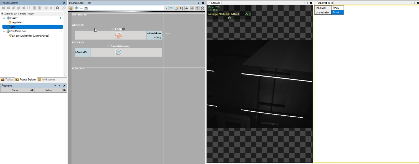
Now you can run the application. The system will alternate the EV7's auxiliary output state every second, generating a rising edge that hardware-triggers the CV60 camera to acquire a frame.
Part D: Using the EV7 Timer Mechanism (Alternative Method)
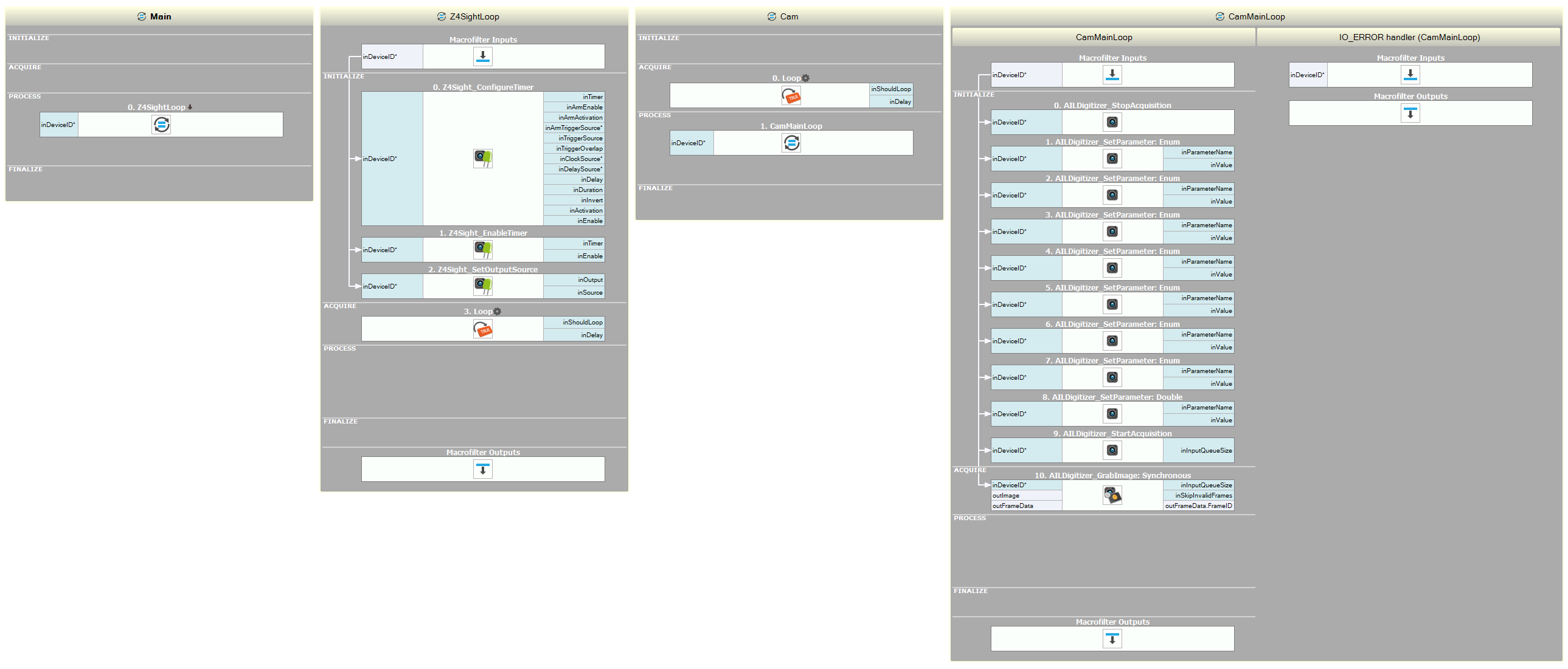
Instead of changing the output value by software as shown in Part A, you can use the EV7 Timer mechanism. To do that:
- Delete all the filters inside the
Mainmacrofilter. - Create a new task macrofilter and name it
"Z4SightLoop". Add it to the PROCESS section of theMainmacrofilter. - Inside the
Z4SightLoop, add these filters to the INITIALIZE section: Z4Sight_ConfigureTimer, Z4Sight_EnableTimer, Z4Sight_SetOutputSource. - Drag and drop the
inDeviceIDinput of one of these tools to the Macrofilter Inputs block to create a new task input. Connect the new input to the rest of the Z4Sight filters. - Go back to the
Mainmacrofilter. Set theinDeviceIDinput values of theZ4SightLoop:- System:
Host - Device:
Default
- System:
- Go back to the
Z4SightLoop. - For the Z4Sight_ConfigureTimer filter, set the
inDelayparameter to5000000000. - For the Z4Sight_SetOutputSource filter, set the
inSourceinput toTimer1. - Add the Loop filter to the ACQUIRE section.
Now you can run the application.
4. References & Media
Hardware Documentation:
