
You are here: Start » Template Matching
Template Matching
Introduction
Template Matching is a high-level machine vision technique that identifies the parts on an image that match a predefined template. Advanced template matching algorithms allow to find occurrences of the template regardless of their orientation and local brightness.
Template Matching techniques are flexible and relatively straightforward to use, which makes them one of the most popular methods of object localization. Their applicability is limited mostly by the available computational power, as identification of big and complex templates can be time-consuming.
Concept
Template Matching techniques are expected to address the following need: provided a reference image of an object (the template image) and an image to be inspected (the input image) we want to identify all input image locations at which the object from the template image is present. Depending on the specific problem at hand, we may (or may not) want to identify the rotated or scaled occurrences.
We will start with a demonstration of a naive Template Matching method, which is insufficient for real-life applications, but illustrates the core concept from which the actual Template Matching algorithms stem from. After that we will explain how this method is enhanced and extended in advanced Grayscale-based Matching and Edge-based Matching routines.
Naive Template Matching
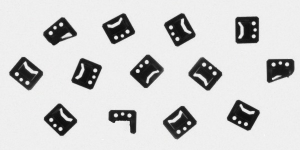
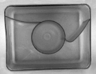
Imagine that we are going to inspect an image of a plug and our goal is to find its pins. We are provided with a template image representing the reference object we are looking for and the input image to be inspected.
 |
 |
|
Template image |
Input image |
We will perform the actual search in a rather straightforward way – we will position the template over the image at every possible location, and each time we will compute some numeric measure of similarity between the template and the image segment it currently overlaps with. Finally we will identify the positions that yield the best similarity measures as the probable template occurrences.
Image Correlation
One of the subproblems that occur in the specification above is calculating the similarity measure of the aligned template image and the overlapped segment of the input image, which is equivalent to calculating a similarity measure of two images of equal dimensions. This is a classical task, and a numeric measure of image similarity is usually called image correlation.
Cross-Correlation
| Image1 | Image2 | Cross-Correlation |
|---|---|---|
|
 |
19404780 |
|
 |
23316890 |
|
 |
24715810 |
The fundamental method of calculating the image correlation is so called cross-correlation, which essentially is a simple sum of pairwise multiplications of corresponding pixel values of the images.
Though we may notice that the correlation value indeed seems to reflect the similarity of the images being compared, cross-correlation method is far from being robust. Its main drawback is that it is biased by changes in global brightness of the images - brightening of an image may sky-rocket its cross-correlation with another image, even if the second image is not at all similar.

Normalized Cross-Correlation
| Image1 | Image2 | NCC |
|---|---|---|
|
|
-0.417 |
|
|
0.553 |
|
|
0.844 |
Normalized cross-correlation is an enhanced version of the classic cross-correlation method that introduces two improvements over the original one:
- The results are invariant to the global brightness changes, i.e. consistent brightening or darkening of either image has no effect on the result (this is accomplished by subtracting the mean image brightness from each pixel value).
- The final correlation value is scaled to [-1, 1] range, so that NCC of two identical images equals 1.0, while NCC of an image and its negation equals -1.0.

Template Correlation Image
Let us get back to the problem at hand. Having introduced the Normalized Cross-Correlation - robust measure of image similarity - we are now able to determine how well the template fits in each of the possible positions. We may represent the results in a form of an image, where brightness of each pixels represents the NCC value of the template positioned over this pixel (black color representing the minimal correlation of -1.0, white color representing the maximal correlation of 1.0).
|
|
 |
|
Template image |
Input image |
Template correlation image |
Identification of Matches
All that needs to be done at this point is to decide which points of the template correlation image are good enough to be considered actual matches. Usually we identify as matches the positions that (simultaneously) represent the template correlation:
- stronger that some predefined threshold value (i.e stronger that 0.5)
- locally maximal (stronger that the template correlation in the neighboring pixels)
 |
 |
 |
|
Areas of template correlation above 0.75 |
Points of locally maximal template correlation |
Points of locally maximal template correlation above 0.75 |
Summary
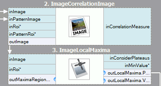
It is quite easy to express the described method in Adaptive Vision Studio - we will need just two built-in filters. We will compute the template correlation image using the ImageCorrelationImage filter, and then identify the matches using ImageLocalMaxima - we just need to set the inMinValue parameter that will cut-off the weak local maxima from the results, as discussed in previous section.
Though the introduced technique was sufficient to solve the problem being considered, we may notice its important drawbacks:
- Template occurrences have to preserve the orientation of the reference template image.
- The method is inefficient, as calculating the template correlation image for medium to large images is time consuming.
In the next sections we will discuss how these issues are being addressed in advanced template matching techniques: Grayscale-based Matching and Edge-based Matching.
Grayscale-based Matching, Edge-based Matching
Grayscale-based Matching is an advanced Template Matching algorithm that extends the original idea of correlation-based template detection enhancing its efficiency and allowing to search for template occurrences regardless of its orientation. Edge-based Matching enhances this method even more by limiting the computation to the object edge-areas.
In this section we will describe the intrinsic details of both algorithms. In the next section (Filter toolset) we will explain how to use these techniques in Adaptive Vision Studio.
Image Pyramid
Image Pyramid is a series of images, each image being a result of downsampling (scaling down, by the factor of two in this case) of the previous element.
|
 |
 |
|
Level 0 (input image) |
Level 1 |
Level 2 |
Pyramid Processing
Image pyramids can be applied to enhance the efficiency of the correlation-based template detection. The important observation is that the template depicted in the reference image usually is still discernible after significant downsampling of the image (though, naturally, fine details are lost in the process). Therefore we can identify match candidates in the downsampled (and therefore much faster to process) image on the highest level of our pyramid, and then repeat the search on the lower levels of the pyramid, each time considering only the template positions that scored high on the previous level.
At each level of the pyramid we will need appropriately downsampled picture of the reference template, i.e. both input image pyramid and template image pyramid should be computed.
 |
 |
 |
|
Level 0 (template reference image) |
Level 1 |
Level 2 |
Grayscale-based Matching
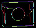
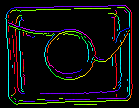
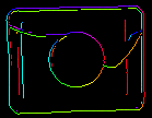
Although in some of the applications the orientation of the objects is uniform and fixed (as we have seen in the plug example), it is often the case that the objects that are to be detected appear rotated. In Template Matching algorithms the classic pyramid search is adapted to allow multi-angle matching, i.e. identification of rotated instances of the template.
This is achieved by computing not just one template image pyramid, but a set of pyramids - one for each possible rotation of the template. During the pyramid search on the input image the algorithm identifies the pairs (template position, template orientation) rather than sole template positions. Similarly to the original schema, on each level of the search the algorithm verifies only those (position, orientation) pairs that scored well on the previous level (i.e. seemed to match the template in the image of lower resolution).
 |
 |
|
|
Template image |
Input image |
Results of multi-angle matching |
The technique of pyramid matching together with multi-angle search constitute the Grayscale-based Template Matching method.
Edge-based Matching
Edge-based Matching enhances the previously discussed Grayscale-based Matching using one crucial observation - that the shape of any object is defined mainly by the shape of its edges. Therefore, instead of matching of the whole template, we could extract its edges and match only the nearby pixels, thus avoiding some unnecessary computations. In common applications the achieved speed-up is usually significant.
| Grayscale-based Matching: | |
 |
 |
|---|---|---|---|
| Edge-based Matching: |  |
 |
 |
Different kinds of template pyramids used in Template Matching algorithms. | |||
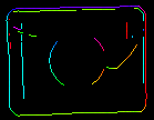
Matching object edges instead of an object as a whole requires slight modification of the original pyramid matching method: imagine we are matching an object of uniform color positioned over uniform background. All of object edge pixels would have the same intensity and the original algorithm would match the object anywhere wherever there is large enough blob of the appropriate color, and this is clearly not what we want to achieve. To resolve this problem, in Edge-based Matching it is the gradient direction (represented as a color in HSV space for the illustrative purposes) of the edge pixels, not their intensity, that is matched.
Filter Toolset
Adaptive Vision Studio provides a set of filters implementing both Grayscale-based Matching and Edge-based Matching. For the list of the filters see Template Matching filters.
As the template image has to be preprocessed before the pyramid matching (we need to calculate the template image pyramids for all possible rotations), the algorithms are split into two parts:
- Model Creation - in this step the template image pyramids are calculated and the results are stored in a model - atomic object representing all the data needed to run the pyramid matching.
- Matching - in this step the template model is used to match the template in the input image.
Such an organization of the processing makes it possible to compute the model once and reuse it multiple times.
Available Filters
For both Template Matching methods two filters are provided, one for each step of the algorithm.
| Grayscale-based Matching | Edge-based Matching | |
|---|---|---|
| Model Creation: | 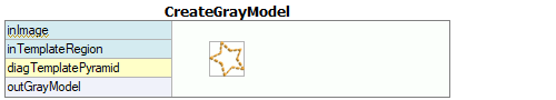 |
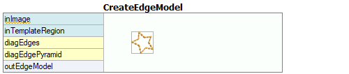 |
| Matching: | 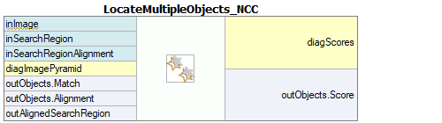 |
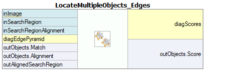 |
Please note that the use of CreateGrayModel and CreateEdgeModel filters will only be necessary in more advanced applications. Otherwise it is enough to use a single filter of the Matching step and create the model by setting the inGrayModel or inEdgeModel parameter of the filter.
The main challenge of applying the Template Matching technique lies in careful adjustment of filter parameters, rather than designing the program structure.
Advanced Application Schema
There are several kinds of advanced applications, for which the interactive GUI for Template Matching is not enough and the user needs to use the CreateGrayModel or CreateEdgeModel filter directly. For example:
- When creating the model requires non-trivial image preprocessing.
- When we need an entire array of models created automatically from a set of images.
- When the end user should be able to define his own templates in the runtime application (e.g. by making a selection on an input image).
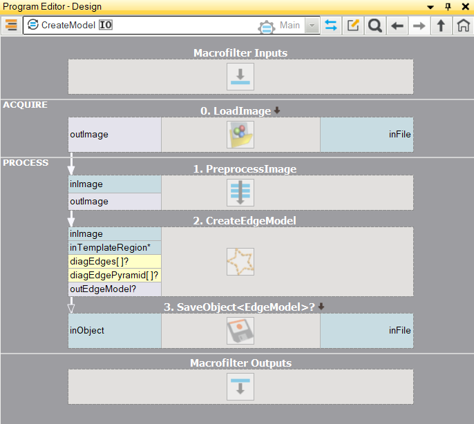
Schema 1: Model Creation in a Separate Program
For the cases 1 and 2 it is advisable to implement model creation in a separate Task macrofilter, save the model to an AVDATA file and then link that file to the input of the matching filter in the main program:
| Model Creation: | Main Program: |
|---|---|
 |
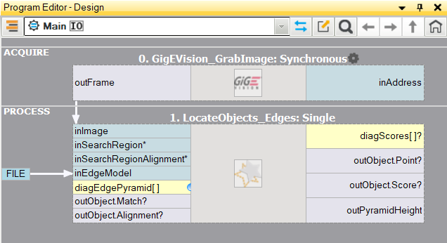 |
When this program is ready, you can run the "CreateModel" task as a program at any time you want to recreate the model. The link to the data file on the input of the matching filter does not need any modifications then, because this is just a link and what is being changed is only the file on disk.
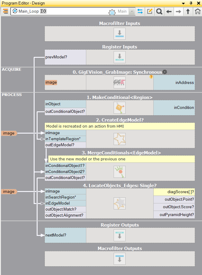
Schema 2: Dynamic Model Creation
For the case 3, when the model has to be created dynamically, both the model creating filter and the matching filter have to be in the same task. The former, however, should be executed conditionally, when a respective HMI event is raised (e.g. the user clicks an ImpulseButton or makes some mouse action in a VideoBox). For representing the model, a register of EdgeModel? type should be used, that will store the latest model. Here is an example realization with the model being created from a predefined box on an input image when a button is clicked in the HMI:
Model Creation
Height of the Pyramid
The inPyramidHeight parameter determines the number of levels of the pyramid matching and should be set to the largest number for which the template is still recognizable on the highest pyramid level. This value should be selected through interactive experimentation using the diagnostic output diagPatternPyramid (Grayscale-based Matching) or diagEdgePyramid (Edge-based Matching).
In the following example the inPyramidHeight value of 4 would be too high (for both methods), as the structure of the template is entirely lost on this level of the pyramid. Also the value of 3 seem a bit excessive (especially in case of Edge-based Matching) while the value of 2 would definitely be a safe choice.
| Level 0 | Level 1 | Level 2 | Level 3 | Level 4 | |
|---|---|---|---|---|---|
| Grayscale-based Matching (diagPatternPyramid): |
 |
 |
 |
 |
 |
| Edge-based Matching (diagEdgePyramid): |
 |
 |
 |
 |
 |
Angle Range
The inMinAngle, inMaxAngle parameters determine the range of template orientations that will be considered in the matching process. For instance (values in brackets represent the pairs of inMinAngle, inMaxAngle values):
- (0.0, 360.0): all rotations are considered (default value)
- (-15.0, 15.0): the template occurrences are allowed to deviate from the reference template orientation at most by 15.0 degrees (in each direction)
- (0.0, 0.0): the template occurrences are expected to preserve the reference template orientation
Wide range of possible orientations introduces significant amount of overhead (both in memory usage and computing time), so it is advisable to limit the range whenever possible.
Edge Detection Settings (only Edge-based Matching)
The inEdgeMagnitudeThreshold, inEdgeHysteresis parameters of CreateEdgeModel filter determine the settings of the hysteresis thresholding used to detect edges in the template image. The lower the inEdgeMagnitudeThreshold value, the more edges will be detected in the template image. These parameters should be set so that all the significant edges of the template are detected and the amount of redundant edges (noise) in the result is as limited as possible. Similarly to the pyramid height, edge detection thresholds should be selected through interactive experimentation using the diagnostic output diagEdgePyramid - this time we need to look only at the picture at the lowest level.
 |
 |
 |
(15.0, 30.0) - excessive amount of noise |
(40.0, 60.0) - OK |
(60.0, 70.0) - significant edges lost |
The CreateEdgeModel filter will not allow to create a model in which no edges were detected at the top of the pyramid (which means not only some significant edges were lost, but all of them), yielding an error in such case. Whenever that happens, the height of the pyramid, or the edge thresholds, or both, should be reduced.
Matching
The inMinScore parameter determines how permissive the algorithm will be in verification of the match candidates - the higher the value the less results will be returned. This parameter should be set through interactive experimentation to a value low enough to assure that all correct matches will be returned, but not much lower, as too low value slows the algorithm down and may cause false matches to appear in the results.
Tips and Best Practices
How to Select a Method?
For vast majority of applications the Edge-based Matching method will be both more robust and more efficient than Grayscale-based Matching. The latter should be considered only if the template being considered has smooth color transition areas that are not defined by discernible edges, but still should be matched.
| Previous: Shape Fitting | Next: Local Coordinate Systems |