
You are here: Start » Function Reference » Computer Vision » 2D Edge Detection » DetectEdges_AsPaths
DetectEdges_AsPaths
| Header: | AVL.h |
|---|---|
| Namespace: | avl |
| Module: | FoundationBasic |
Extracts subpixel-precise paths that represent continuous edges.
Applications: Consistent detection of contours of variable or unpredictable shape, e.g. screw thread outline or a custom piece of textile.
Syntax
void avl::DetectEdges_AsPaths
(
	const avl::Image& inImage,
	atl::Optional<const avl::Region&> inRoi,
	avl::EdgeFilter::Type inEdgeFilter,
	float inStdDevX,
	atl::Optional<float> inStdDevY,
	float inEdgeThreshold,
	float inEdgeHysteresis,
	atl::Optional<float> inMaxJoiningDistance,
	float inMaxJoiningAngle,
	float inJoiningDistanceBalance,
	atl::Optional<float> inJoiningEndingLength,
	float inMinEdgeLength,
	atl::Array<avl::Path>& outEdges,
	avl::Image& diagGradientMagnitudeImage,
	avl::Region& diagEdgeRegion
)
Parameters
| Name | Type | Range | Default | Description | |
|---|---|---|---|---|---|
 |
inImage | const Image& | Image from which edges will be extracted | ||
|
inRoi | Optional<const Region&> | NIL | Region of the image from which edges will be extracted | |
|
inEdgeFilter | EdgeFilter::Type | Type of edge filter used for computing gradients | ||
|
inStdDevX | float | 0.0 -  |
2.0f | Amount of horizontal smoothing used by the edge filter |
|
inStdDevY | Optional<float> | 0.0 - |
NIL | Amount of vertical smoothing used by the edge filter (Auto = inStdDevX) |
|
inEdgeThreshold | float | 0.0 - |
15.0f | Sufficient edge strength; edges of that strength will always be detected |
|
inEdgeHysteresis | float | 0.0 - |
5.0f | Value by which the edge threshold is decreased for edge points neighboring with sufficiently strong edges |
|
inMaxJoiningDistance | Optional<float> | 0.0 - |
NIL | Maximal distance between edges that can be joined |
|
inMaxJoiningAngle | float | 0.0 - 180.0 | 30.0f | Maximal allowed angle between edges being joined |
|
inJoiningDistanceBalance | float | 0.0 - 1.0 | 0.0f | Determines how important distance between edges is according to their angle difference |
|
inJoiningEndingLength | Optional<float> | 1.0 - |
NIL | Determines the length of the edge end used for edge angle computing |
|
inMinEdgeLength | float | 0.0 - |
0.0f | Minimal length of an edge |
 |
outEdges | Array<Path>& | Paths representing found edges | ||
 |
diagGradientMagnitudeImage | Image& | Visualization of the gradient magnitude | ||
|
diagEdgeRegion | Region& | Region representing found edges |
Description
The operation extracts edges from the inRoi region in the inImage image and stores the result in the array of paths outEdges. The extraction process is the same as in DetectEdges_AsRegion, the only difference being the data type of the result. This filter returns an array of subpixel-precise paths rather than region computed by DetectEdges_AsRegion.
The extraction process starts from gradient computing. Depending on which edge filter is chosen, gradients are computed using recursive (Deriche or Lanser) or standard non-recursive filter proposed by Canny. The inStdDevX and inStdDevY parameters control size of the filter mask. The greater their values are, the larger this size is. It should be noted that the execution time of the non-recursive filter depends greatly on the size of the filter mask, while the recursive filters execution time is independent of it.
On the so computed gradient image threshold with hysteresis (as in ThresholdImage_Hysteresis) is performed with inEdgeThreshold and inEdgeHysteresis parameters. After this step only gradients which are strong enough are present. The resulting edge region can be much too thick, thus it has to be thinned. To achieve this, the non-maximum suppression is used. Every pixel with at least one of its neighbors having larger gradient is no longer considered to be an edge pixel (only neighbors in the direction of pixel's gradient matter).
The positions of found edges are then determined with subpixel precision. The so extracted edges can then undergo further post-processing, if necessary. An edge can be joined with another one in its vicinity, but only if the distance between them is not greater than inMaxJoiningDistance and neither of them forms an angle greater than inMaxJoiningAngle with the segment connecting their endings. The inJoiningEndingLength parameter determines what part of the edge ending is used to determine above mentioned turn angle. If it is set to Nil, only the last edge segment is decisive. Sometimes two or more edges can be joined with an edge. Because only one of them can be, each of the candidates is evaluated based on the distance from the fixed edge's ending and the turn angle associated with their connection. The greater inJoiningDistanceBalance is, the less influence on the evaluation score the latter value has. After the joining phase, edges that are shorter than inMinEdgeLength are removed from the final results.
Hints
- Connect an input image to the inImage input.
- Start with inEdgeHysteresis = 0 and set inEdgeThreshold so that each important edge is at least partially detected. Then keep increasing inEdgeHysteresis until the edges are detected completely.
- If the edges are rugged or there are too many false edges, then try increasing inStdDevX.
- Do not change inEdgeFilter.
- Define inMaxJoiningDistance and inMaxJoiningAngle to fix small discontinuities in the resulting edges. This may be very useful when some gaps appear due to noise, dust or other irregularities that preclude correct object detection.
- Sometimes some of the edges being joined have bent endings and inMaxJoiningAngle would have to be large. Increase inJoiningEndingLength to 3-5 to improve that.
- Use inMinEdgeLength to remove short edges that appear due to noise.
Examples
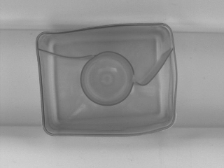 |
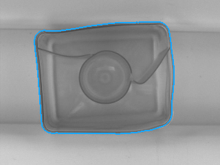 |
DetectEdges_AsPaths performed on the sample image with inEdgeFilter = Canny, inStdDevX = 2.5, inStdDevY = 2.5, inEdgeThreshold = 10, inEdgeHysteresis = 5, inMinEdgeLength = 1000.
Hardware Acceleration
This operation supports automatic parallelization for multicore and multiprocessor systems.
See Also
- DetectEdges_AsRegion – Extracts a pixel-precise region of continuous edges.
- DetectEdges_AsRegion_Mask – Extracts a pixel-precise region of continuous edges. Faster, yet less accurate version.
- DetectEdges_AsPaths_Mask – Extracts subpixel-precise paths that represent continuous edges. Faster, yet less accurate version.