
You are here: Start » User Interface » Creating Models for Template Matching
Creating Models for Template Matching
Introduction
Template Matching tools are very often used as one of the first steps in industrial inspection applications. The goal is to detect the location of an object. Before this can be done the user has to create a model representing the expected object's shape or structure. To make this step straightforward, Adaptive Vision Studio provides an easy user interface. We call it a "GUI for Template Matching".
The GUI for Template Matching is an editor for values of two types:
EdgeModel and
GrayModel.
This means that to open it the user has to select a template matching filter in the program
and then click on the  button at the inGrayModel or inEdgeModel
input in the Properties window:
button at the inGrayModel or inEdgeModel
input in the Properties window:
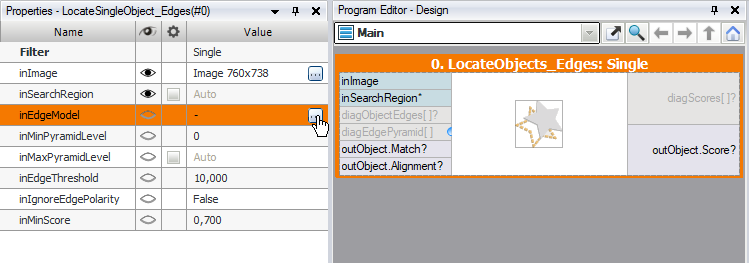
Opening GUI for Template Matching.
In majority of industrial applications Template Matching algorithms implemented in Adaptive Vision Studio easily detect the location of an object using default parameters. However, there are cases where it is needed to tune some of them, mainly in order to achieve higher reliability. It turned out that there is a group of parameters, which is used more often than others. Therefore GUI for Template Matching is available in two variants: Basic and Expert. This is related to Complexity Levels available in Adaptive Vision Studio.
Creating a Model
Basic
The Basic window contains the following elements:
- At the top: a list of possible template images
- Below: a simple toolbar that also contains a button for loading a template image from a file
- On the left: a tool for selecting a rectangular template region
- On the right: track-bars for setting parameters and some options related to the view
- In the center: an area for selecting the template region in the context of the selected template image
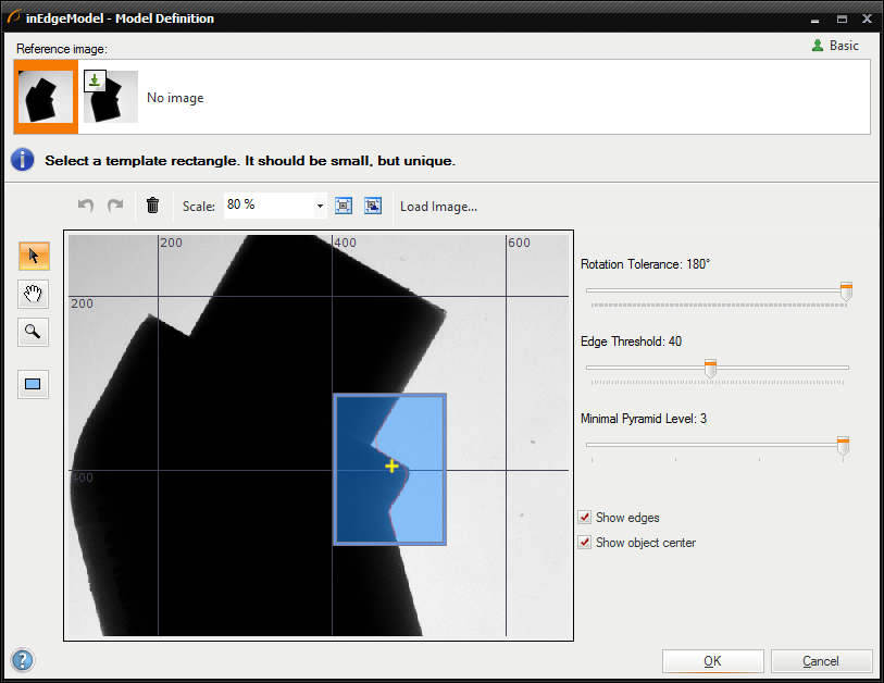
Basic GUI for Template Matching window
To create a template matching model you need to:
- Choose a template image from the "Reference image" list.
- Select a rectangular template region using
 drawing tool.
For maximum performance this rectangle should be as small as possible.
drawing tool.
For maximum performance this rectangle should be as small as possible.
- Edge-based matching only: Set the Edge Threshold parameter, which should be set to value that results in the best quality of the edges. Edge Threshold determines
the minimum strength (gradient's magnitude) of pixels that can be considered as an edge.
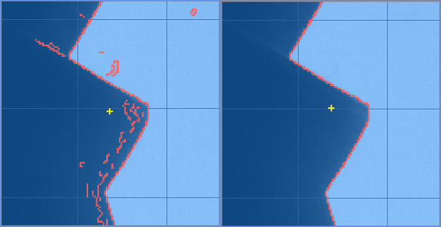
Low quality edges (Edge Threshold = 8) and high quality edges (Edge Threshold = 30)
- Set the Rotation Tolerance in range from 0° to 360°. This parameter determines the maximum expected object rotations. Please note that the smaller the Rotation Tolerance, the faster the matching.
- Set the Minimal Pyramid Level parameter which determines the lowest pyramid level used to validate candidates who were found on the higher levels. What is worth mentioning is that setting this parameter to a value greater than 0 may speed up the computation significantly, however, the accuracy of the matching can be reduced. More detailed information about Image Pyramid is provided in Template Matching document in our Machine Vision Guide.
Expert
The Expert window contains the following elements:
- At the top: a list of possible template images
- Below: a simple toolbar that also contains a button for loading a template image from a file
- On the left: a tool for selecting a template region of any shape
- On the right: parameters of the model, their description and some options related to the view
- In the center: an area for selecting the template region in the context of the selected template image
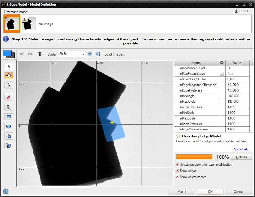
GUI for Template Matching window
To create a template matching model you need to:
- Choose a template image from the "Reference image" list.
- Mark a template region using drawing tools (please note, that the button above the tools switches the current color, i.e. you can both draw or erase shapes). For maximum performance this region should be as small as possible.
- Edge-base matching only: Set the inSmoothingStdDev, inEdgeMagnitudeThreshold and inEdgeHysteresis parameters to values that result in the best quality of the found edges.
It is advisable to first set inEdgeHysteresis to zero, then choose a value for inEdgeMagnitudeThreshold that assures that all edges have some
parts detected and then increase inEdgeHysteresis. Small noise might by removed by change the value of parameter inSmoothingStdDev. For example:
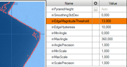
Low quality edges
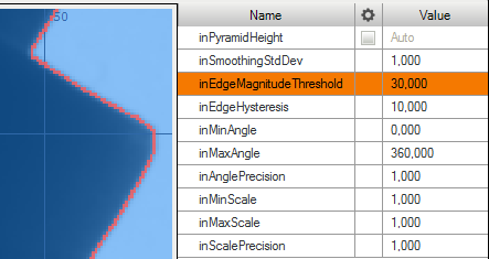
High quality edges
- Set the inMinAngle and inMaxAngle parameters accordingly to the expected range of object rotations (the smaller the range, the faster the matching).
- Set the inAnglePrecision to a value lower that 1.0 if you prefer to lower the angular precision for the benefit of speed.
- Set the inMinScale, inMaxScale and inScalePrecision to appropriate value if you need to detect objects in different scale. You should be aware of longer detection time when you detect objects in scale.
- Click the "Refresh" button or check "Update preview after each modification" to review the results.
- Click the "Next >" button to select template rectangle that represents the entire object of interest (the expected result of matching)
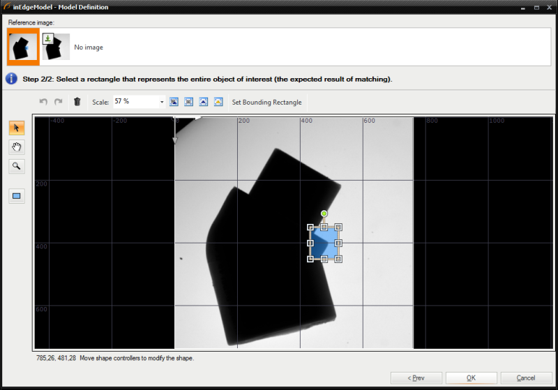
Template rectangle selection
- Click "OK" to close the window and generate the model.
Performing Template Matching
When the model is ready, performing template matching in an application is straightforward – after connecting the filters and setting the matching parameters, the results are on the outputs of the LocateSingleObject_Edges filter (or similar):
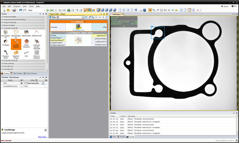
Example result of template matching
See also:
Template Matching guide, Template Matching filters| Previous: Creating Macrofilters | Next: Preparing Rectification Transform Map |