
You are here: Start » Program Examples » Pins
Pins
Aim
The task is to measure distances between consecutive pins and how far away they are from the center.
Input
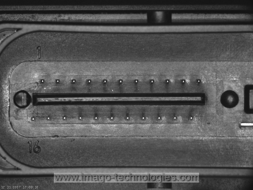
An image in which pins are present.
Output
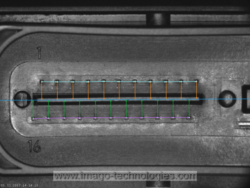
A set of measured distances and an image where the measured distances are drawn.
Hints
The pins are the brightest elements of the image as well as the smallest. Using ImageLocalMaxima would allow to find their locations. To measure distances PointSequenceDistances can be used.
Solution (AVS)
-
Add EnumerateImages filter to get load consecutive images of some disk directory.
-
While the pins are one of the brightest elements in the image, there are also other similarly bright elements. To filter those unwanted elements out add a DifferenceOfGaussians filter. This filter will calculate the difference between two smoothed images. Since pins are very small and surrounded by dim background they should disappear after strong smoothing.
- Set the inStdDev parameter to 2.
-
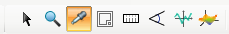
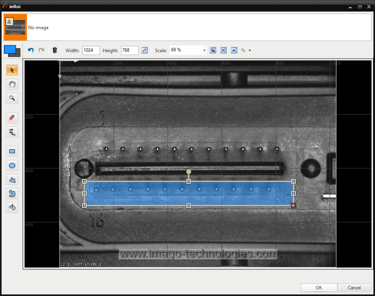
Run the program once and drag the output of the filter to the preview. As you can see only the pins are visible in the image and the rest of the image is very dark. Now use the color picker tool (from the panel shown in the image below) and check the pins' brightness. Each pin has brightness of at least 40 and no other element is so bright. The picture below shows where the picker tool can be found.
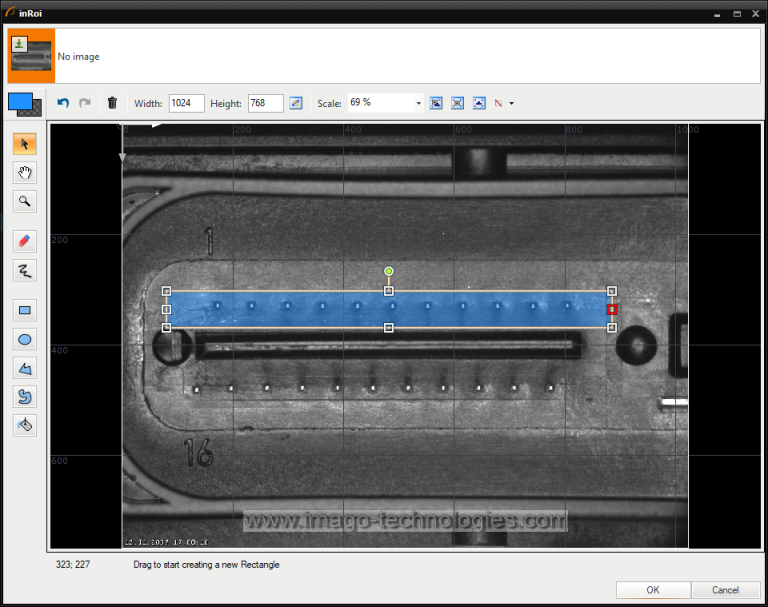
- Now add an ImageLocalMaxima filter and set the inMinValue parameter to 40. In this step we want to measure only the upper row of pins, so click on the "..." icon next to inRoi in the Properties window to open the editor. After that choose the image from EnumerateImages as the reference image (in the top bar of the editor) and draw a rectangle around the upper row of pins (see picture below). Close the editor, drag the outLocalMaxima.Point output to the preview and run the program once again.
-
Now you can see the detected points in the preview. However, they are not sorted. To sort them from left to right add a SortArray filter of type Point2D. Connect the outLocalMaxima.Point to inArray. To change the order of the points along a horizontal axis we need only their x coordinates. Right click outLocalMaxima.Point and choose Property outputs and the X. Connect the newly created output to inValues.
-
In the following steps we will need to know the segment which is formed by the top row pins. To fit a segment to points a FitSegmentToPoints filter and connect outSortedArray to its input.
-
Now we can measure the distance between the consecutive points. We can do it by using PointSequenceDistances. Add it and connect outSortedArray to its input.
-
Now we need to do the same for the bottom row. The easiest way to to do this is by making a custom macrofilter and copying it. Select all the blocks after EnumerateImages, right click them and select Extract step....
- You can change the name of the filter. Here it is named "InspectRowOfPins".
- Enter the filter and drag the inRoi input to the top bar of the filter ("Macrofilter Inputs"). Now the ROI can be changed outside the filter.
- Now drag outConnectingSegments, outDistances and outSortedArray to the "macrofilter Outputs" bar to make new outputs.
-
Go back up to the Main filter of the program. Now select the newly created macrofilter and copy it so that you have two instances of it.
-
Since you created the inRoi input, you have to once again select the region in which the pins are. For the first filter select the region corresponding to the upper row and for the second filter - the bottom row.
-
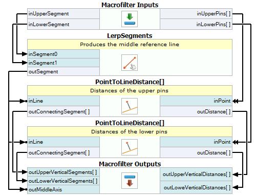
The program calculates distances between consecutive points of one row. Now we need to measure the distance to the center. To find the centerline add a LerpSegments filter. Set its inIgnoreOrientation to True. Connect outConnectingSegments of both the InspectRowOfPins macrofilters to its inputs inSegment0 and inSegment1.
-
Add a PointToLineDistance filter. Connect the outSortedArray output of one of the InspectRowOfPins macrofilter to the inPoint input. Then connect outSegment to inLine.
-
Now repeat the previous step but this time connect the outSortedArray from the second macrofilter.
-
The program now calculates the distances between points and the centerline.
-
Create another macrofilter from the last three blocks. Make sure it returns all the important data. Then drag the outputs to the preview.
- It is good practice to name the ports of macrofilters in a descriptive way. For example, notice how the ports are named in the example program.
Macrofilter Main
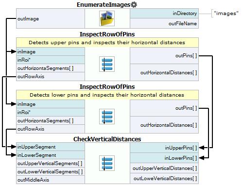
Macrofilter InspectRowOfPins

Macrofilter CheckVerticalDistances
Used Filters
| Icon | Name | Description |
|---|---|---|
| SortArray | Changes the order of the input array elements accordingly to an ascending/descending sequence of the value array. | |
| EnumerateImages | Emulates image acquisition with images stored on disk. | |
| FitSegmentToPoints | Finding a locally optimal segment. Good enough when the number of outliers is small. | |
| LerpSegments | Linearly interpolates between two segments. | |
| PointSequenceDistances | Measures the distances between consecutive points of a point sequence. | |
| PointToLineDistance | Measures the distance between a point and a line. | |
| ImageLocalMaxima | Detection of characteristic points, usually after some image transformations. | |
| DifferenceOfGaussians | Emphasizes high-frequency image features such as lines or patches / dots. |
Further Readings
- Shape Fitting - This article presents usage of the Shape Fitting technique.