
You are here: Start » Program Examples » Cap (Advanced)
Cap (Advanced)
Aim
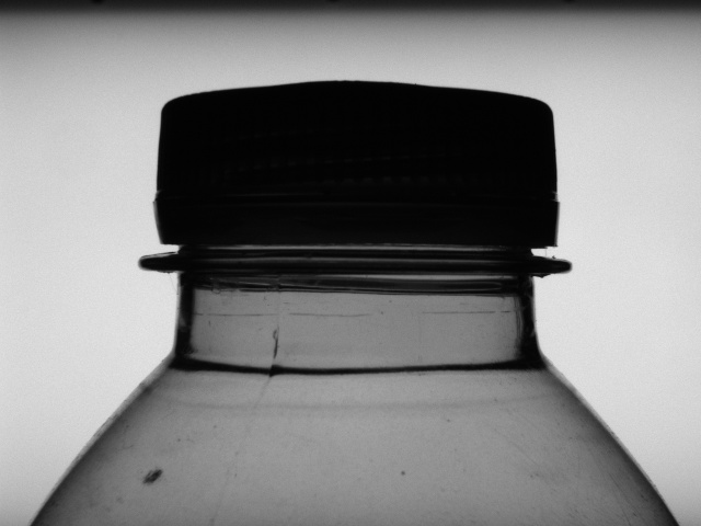
The task of this example is to check whether a seal (plastic ring under the cap) is correctly placed.
Input
An image of the top of a bottle. The position of the bottle is variable.
Output
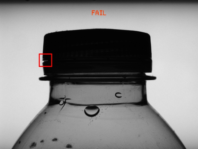
The result of the inspection printed on the image. If a defect is detected, a rectangle is drawn around it.
Hints
The position of the object is variable along both vertical and horizontal axes. Using 1D Edge Detection technique you are able to create a local coordinate system that can be used to configure other tools to work independent of the object orientation, translation and scale.
Solution (AVS)
-
Add an EnumerateImages filter to get load consecutive images of some disk directory.
-
Add a ScanSingleStripe filter to detect the position of a cap along the X axis.
- Click the "..." button at the inScanPath input to open the GUI for drawing paths of scanning. Draw a horizontal path that intersects the cap roughly at the vertical center of the cap. The path should have the same length as an image width. Click OK to close the GUI.
- In filter parameters set the value of MinStripeWidth to slightly less than the expected diameter of the cap (here 300 should be enough). Make sure the StripePolarity parameter is set to Dark.
- Click on Show/Hide Ports at the bottom of the filter and check the options Width, Point1 and Point2 in the outStripe submenu. This will allow us to see the width of the detected stripe as well as both edge points.
-
Add a CreateCoordinateSystemFromPoint filter and connect outStripe.Point1 from the previous filter to the inPoint in this filter.
- In the Properties of the filter click on the eye icon next to inScale. Now the input port for this parameter is visible. Connect to it the outStripe.Width parameter from the previous filter.
- In the inScaleDivisor field enter 360. This is the diameter of the reference cap on which next steps of the program are based. Note that the position of a cap also varies along an axis perpendicular to the image, but creating the coordinate system in this way ensures that the scale will adjust to the width of the cap. In other words, if the cap is closer to the camera, the scale increases.
-
Run the program once and then add a ScanSingleEdge filter. Connect outCoordinateSystem output from the previous filter to the inScanPathAlignment input.
- Click the "..." button at the inScanPath. In the GUI make sure the Coordinate System is set to inScanPathAlignment. Draw a vertical scan path which intersects with the cap roughly in its highest point. Click OK to close the editor.
- Show the outCoordinateSystem.Scale output by clicking on Show/Hide Ports and check the options Point in the outEdge submenu.
-
Add a Formula block. Drag onto it the outStripe.Point1 output and click OK to create a formula input.
- Do the same for the outEdge.Point and outCoordinateSystem.Scale.
- After dragging an output we recommend you to change the default name that will be used in formula. Here the name inCoordinateSystemScale was shortened to just inScale. Name of inputs must begin with the letters "in".
- Click on Add Output. Choose a name of this output and set the type to CoordinateSystem2D.
- Now you can create a Coordinate System inside a Formula using the constructor of CoordinateSystem2D data type.
- The constructor requires three inputs: an origin (Point2D), an angle (Real) and a scale (Real).
- The scale is equal to inScale.
- The angle is equal to 0.
- The origin is equal to a point whose x coordinate is equal to the x coordinate of inPoint1, the y coordinate is equal to the y coordinate of inPoint2.
- Click OK to finish creating an output.
-
In the Project Explorer section click Create New Global Parameter.... Choose a name for the variable and set the type to Segment2DArray.
- Click the plus icon below Initial Value. Then click Add New Item and the "..." icon in the newly created item. This will open a segment editor.
- In the editor first choose the image from EnumerateImages as the reference image. Next set the Coordinate system field to the output of the previously created formula and finally draw a vertical segment intersecting with cap at roughly one fourth of its width. Click OK.
- Now add two new items, each being a Segment2D: one at the center and one at three fourths of the width:
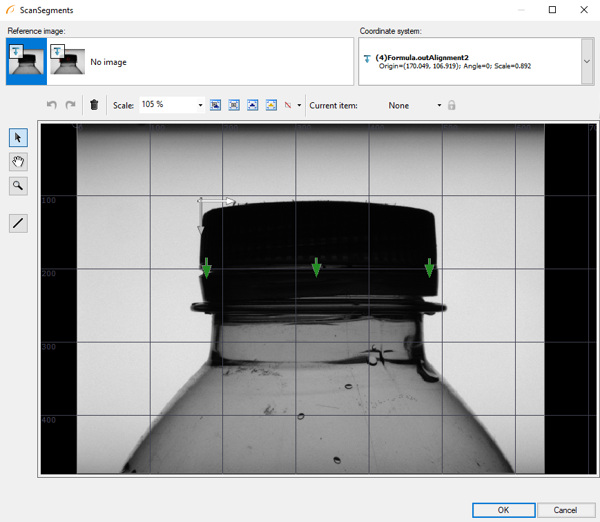
- Click OK to finish creating a global parameter.
-
Run the program once and then add another ScanSingleEdge filter.
- Connect the previously created global parameter to the inScanPath input by dragging it from the Project Explorer section.
- Connect the output of the formula to the inScanPathAlignment input.
- Notice that the name of the filter is now followed by a suffix: "[3]". This indicates that the filter will run 3 times in one iteration of the program: once for each segment the array (the global parameter).
- In filter properties change EdgeTransition to DarkToBright. Also, lower MinMagnitude to 4 from 5.
- Show the outEdge.IsNil output by clicking on Show/Hide Ports and check the options Point in the outEdge submenu. This will tell if the edge was detected.
-
Add another Formula filter. Its only input will be outEdge.IsNil from the previous filter.
- Create a new output of type Bool (here named outIsOK).
- The formula for the output is shown in images. The bottle will pass only if there are no gaps detected.
- Create another output, this time of type String (here named outResultText).
- Using conditional operators create a formula, where the text will read "PASS" if the input condition is True or "FAIL" if the input is False.
-
Add a DrawStrings_TwoColors filter.
- Connects outResultText to inStrings and outIsOK to inConditions.
- In the filter properties click on the "..." icon next to inLocations to open the editor.
- Put a single point roughly in the upper center of the image.
- Other properties can be modified to change the color of the text and its size. Here inSize is set 24.
-
Add a CreateBox filter.
- Connect outEdge.Point to inLocation.
- Set the size of the rectangle by using setting inWidth and inHeight to constant Values (here 40 and 40).
-
Add a DrawRectangles_SingleColor filter. In Properties window the appearance of the rectangle can be changed.
-
Select the last 3 filters in the program (from DrawStrings_TwoColors).
- Right click on them and select the ExtractStep... option.
- Now you can change the name of the macrofilter (here: DrawResults)
- By right clicking inputs and outputs of this filter and then clicking edit, you can change names and types of the ports.
-
Enter the newly created filter and drag outImage to the Macrofilter Outputs bar.
-
Drag the output from the created filter to the preview.
-
Now the final output of the whole program should be the image with the inspection result label and defects marked with rectangles.
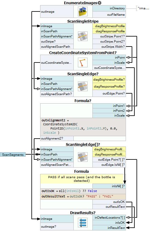
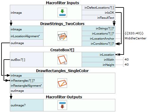
Macrofilter Main
Macrofilter DrawResults
Used Filters
| Icon | Name | Description |
|---|---|---|
| EnumerateImages | Emulates image acquisition with images stored on disk. | |
| CreateBox | Creates a box. | |
| DrawStrings_TwoColors | Draws strings (text) on an image with two colors, depending on the status of each string (usually: green or red for pass/fail status). | |
| ScanSingleStripe | Very fast detection or measurement of an object defined by a pair of opposite edges. | |
| CreateCoordinateSystemFromPoint | Most often used to define an object alignment from results of 1D Edge Detection or Blob Analysis. | |
| ScanSingleEdge | Very fast detection of an object (e.g. horizontal displacement of a bottle) and simple measurements (e.g. liquid level in a bottle). | |
| DrawRectangles_SingleColor | Draws rectangles on an image with a single color. |
Further Readings
- 1D Edge Detection - The article explaining how edge detection filters work.
- Local Coordinate Systems - This article describes basic concept of using the coordinate systems.
- Formulas - Detailed information about using formulas.