
You are here: Start » AVL.NET » AVL.CalibrateWorldPlane
AVL.CalibrateWorldPlane
Finds the image to world plane transformation matrix.
| Namespace: | AvlNet |
|---|---|
| Assembly: | AVL.NET.dll |
Syntax
public static void CalibrateWorldPlane
(
	IList<AvlNet.Point2D> inImagePoints,
	IList<AvlNet.Point2D> inWorldPlanePoints,
	AvlNet.RectificationTransform outTransform,
	out float outRmsError,
	out float outMaxReprojectionError,
	IList<AvlNet.Segment2D> outReprojectionErrorSegments
)
Parameters
| Name | Type | Range | Default | Description | |
|---|---|---|---|---|---|
 | inImagePoints | System.Collections.Generic.IList<AvlNet.Point2D> | Array of 2D points of the calibration pattern, in the picture. | ||
| inWorldPlanePoints | System.Collections.Generic.IList<AvlNet.Point2D> | Array of 2D points of the calibration pattern, in a given world coordinate plane. | ||
 | outTransform | AvlNet.RectificationTransform | |||
| outRmsError | float | RMS reprojection error, in pixels. | ||
| outMaxReprojectionError | float | Maximum reprojection error, in pixels. | ||
| outReprojectionErrorSegments | System.Collections.Generic.IList<AvlNet.Segment2D> | Array of segments connecting input image points to reprojected world points. |
Description
The filter estimates the correspondence between the image plane and a "world plane" – a given planar surface in observed space. The image plane, and thus inImagePoints are assumed to be distorted, and to correct for the distortion the inCameraModel (calibration data) needs to be provided. The calculated result – outTransform contains all the information for transforming the distorted image plane to the world plane.
The inCameraModel is also used to define the type of the planar correspondence. For a standard projective camera (pinhole camera), the planar correspondence is a homography. If the inCameraModel is a telecentric camera, the planar correspondence is affine (as there are no perspective parameters in orthographic projection). If no inCameraModel is provided, the filter defaults to homography.
The homography requires at least four inImagePoints (and their inWorldPlanePoints correspondences). The affine relation requires at least three such pairs.
Grids detected by some filters such as DetectCalibrationGrid_Chessboard have random origin location. When using such grids as a source of inImagePoints and inWorldPlanePoints, the inWorldPlaneOrigin and inWorldPlaneXAxis can be used to set the origin and x axis direction for the world plane. Note that the origin and the axis direction does not need to lie on a grid point, it can be arbitrarily chosen.
The filter provides a few methods for judging the feasibility of calculated solution.
- The outRmsError and outMaxReprojectionError. The main contributor to these values is the random noise in inImagePoints positions. Model mismatch (i.e. trying to calibrate a non-planar object, e.g. wavy surface) will also result in increased reprojection errors. Large difference between outRmsError and outMaxReprojectionError could be a sign of presence of outliers in input data.
- The outReprojectionErrorSegments consists of segments connecting input image points to reprojected world points, and thus it can be readily used for visualization of per-point reprojection errors.
Examples
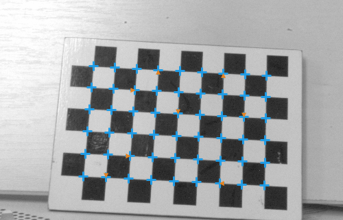
Good case of image to world plane calibration using high amount of calibration points. Calibration resulted in RMS and maximum reprojection errors less than 1.0, as expected. The outReprojectionErrorSegments are not visible at that scale.

Example of a gross error. The RMS reprojection error is 17.6, max reprojection error is 91.2, source of these errors is clearly visible thanks to outReprojectionErrorSegments: the association of inImagePoints and inWorldPlanePoints is wrong.
Errors
List of possible exceptions:
| Error type | Description |
|---|---|
| DomainError | Array inImagePoints and inWorldPlanePoints sizes differ |