
You are here: Start » Program Examples » WebHMI - Beam Scale Precision Level
WebHMI - Beam Scale Precision Level
Aim
The task is to create a program that will help in precise calibration of a traditional beam scale as well as precise measurements using the scale. The program should include a simple WebHMI capable of not only displaying the results in real time but also simple control of the displayed elements and tolerance value.
The program should detect the position of the beam and calculate its deviation from the center (zero).
Input
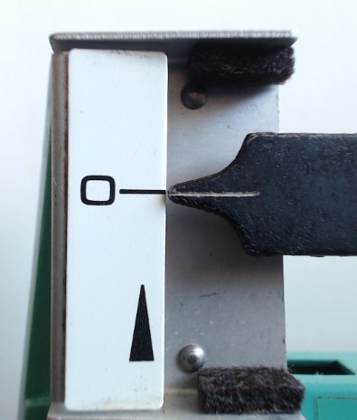
Image of a beam scale.
Output
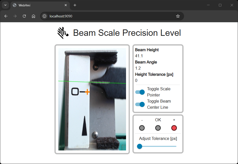
WebHMI containing the image with zero position, current beam position, position values as well as toggle buttons and a slider allowing for turning the displayed elements on/off and setting the tolerance value in pixels.
Hints
Local coordinate system
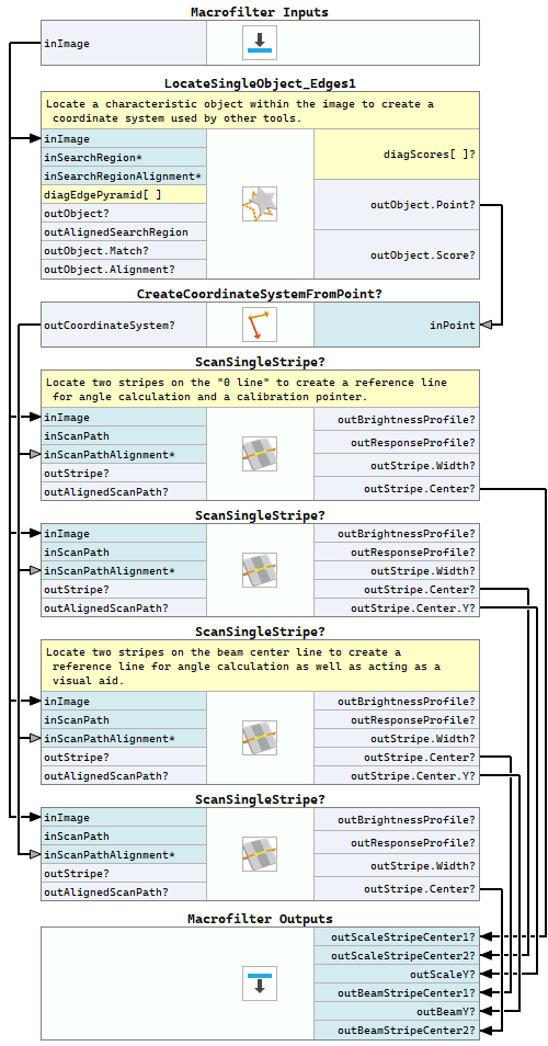
Since the camera used for image acquisition might not be mounted in a fixed position, it is often necessary to use Template Matching and create a local coordinate system, which will be later used for beam scale and zero marking detection with an appropriate translation. This reduces the need for near-perfect camera placement every time. For this purpose you can use the LocateSingleObject_Edges1 filter.
Detecting beam position
The simplest way to detect beam position and the zero value marked on the scale is to use the 1D Edge Detection techniques.
To calculate the beam's deviation from zero (measured in pixels), you need to find the dead center of the beam tip as well as the zero marking line
using the ScanSingleStripe filter. Next, we can use the Y coordinate the beam's stripe center and compare it with Y value of the
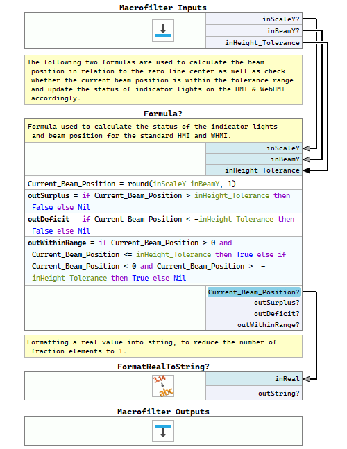
scale's zero line stripe center. The final calculation of the current beam position can be done within a formula.
Additional graphical elements
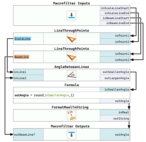
Please note, that we use two instances of the ScanSingleStripe filter both for the zero line as well as the beam tip to be able to draw the zero line and beam center line, display these lines in the WebHMI image as well as calculate the angle between them.
WebHMI
Information on designing WebHmi and WebHMI Event Handling mechanism can be found in this section.
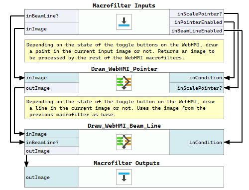
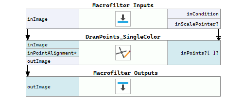
Since WebHMI does not have a control capable of displaying both image and some other data, like 2D Primitives, it is necessary to prepare the final image before sending it to the WebHMI. This is done within the DrawHMI macrofilter containing two variant macrofilters, responsible for adding different elements (point and line) to the image depending on the state of the toggle buttons on the WebHMI.
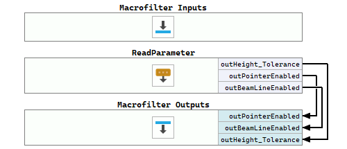
The current state of the WebHMI toggle buttons and slider is stored within global parameters and passed to different macrofilters. More about global parameters can be learned from this article. The global parameters are read at the beginning of every program iteration.
Labeling
For the purpose of better program clarity, labeled connections are used. Labeling connections is explained in this article.
Solution (AVS)
Macrofilter Main.
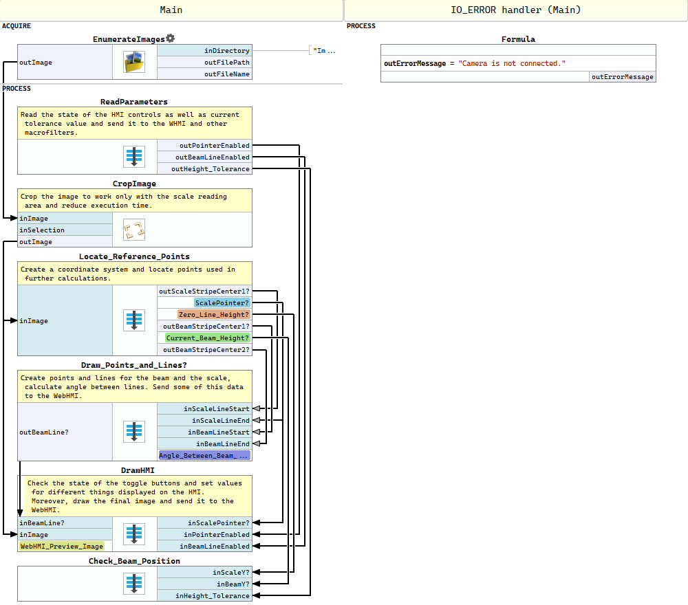
Macrofilter ReadParameters
Macrofilter Locate_Reference_Points
Macrofilter Draw_Points_and_Lines
Macrofilter DrawHMI
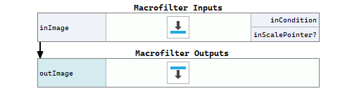
Macrofilter Draw_WebHMI_Pointer(True)
Macrofilter Draw_WebHMI_Pointer(False)
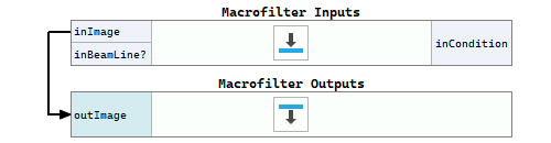
Macrofilter Draw_WebHMI_Beam_Line(True)
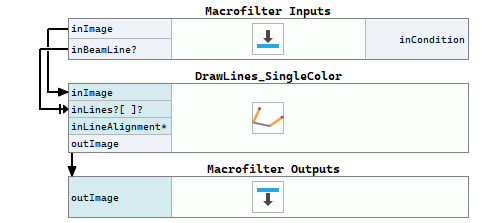
Macrofilter Draw_WebHMI_Beam_Line(False)
Macrofilter Check_Beam_Position
Macrofilter OnSwitch_Button_1_Checked
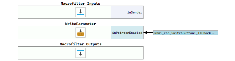
Macrofilter OnSwitch_Button_1_Unchecked

Macrofilter OnSwitch_Button_2_Checked
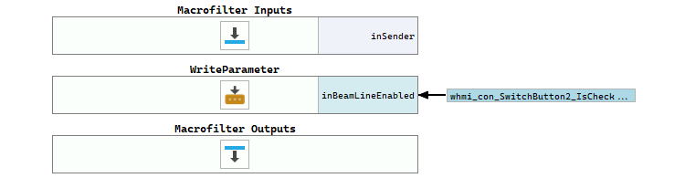
Macrofilter OnSwitch_Button_2_Unchecked

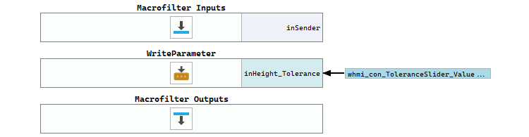
Macrofilter OnToleranceSlider_ValueChanged
Further Readings
- 1D Edge Detection - The article explaining how edge detection filters work.
- Local Coordinate Systems - This article describes basic concept of using the coordinate systems.
- Formulas - Detailed information about using formulas.
- WebHMI Controls - List of WebHMI controls.